Table of Contents
7-Segment LED Display
A seven segment display can be used to display the decimal number 0-9 and some alpha characters.

Each of the seven LEDs is called a segment. An additional 8th LED is sometimes used within the same package to indicate of a decimal point (DP).
A 7 segment display is made of seven different illuminating segments. These are arranged in a way to display numbers and characters by different combinations of segments. The binary information is displayed using these seven segments. LED or light emitting diode is P-N junction diode which emits the energy in the form of light.
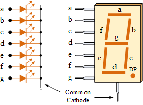
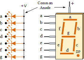
Seven segment display are generally made up of LEDs. These LEDs glow when they are forward biased. The intensity of the LEDs depends on forward current. So, sufficient forward current has to be provided to these LEDs to glow with full intensity. In segment displays common pin is generally used to identify which type of 7-segment display it is. As each LED has two connecting pins, one called the “Anode” and the other called the “Cathode”, there are therefore two types of 7-segment display called: Common Cathode (CC) and Common Anode (CA).
The difference between the two displays, as their name suggests, is that the common cathode has all the cathodes of the 7-segments connected directly together and the common anode has all the anodes of the 7-segments connected together and is illuminated as follows.

1. The Common Cathode (CC)
In the common cathode display, all the cathode connections of the LED segments are joined together to logic “0” or ground. The individual segments are illuminated by application of a “HIGH”, or logic “1” signal via a current limiting resistor to forward bias the individual Anode terminals (a-g).
2. The Common Anode (CA)
In the common anode display, all the anode connections of the LED segments are joined together to logic “1”. The individual segments are illuminated by applying a ground, logic “0” or “LOW” signal via a suitable current limiting resistor to the Cathode of the particular segment (a-g).
In general, common anode displays are more popular as many logic circuits can sink more current than they can source A common cathode display can’t replace in a circuit of a common anode display and vice versa, as it is the same as connecting the LEDs in reverse, and hence light emission will not take place.
Depending upon the decimal digit to be displayed, the particular set of LEDs is forward biased. For instance, to display the numerical digit 0, we will need to light up six of the LED segments corresponding to a, b, c, d, e and f. Thus the various digits from 0 to 9 can be displayed using a 7-segment display.
7-Segment Display Segments for all Numbers
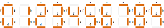
Then for a 7-segment display, we can produce a truth table giving the individual segments that need to be illuminated in order to produce the required decimal digit from 0 through 9 as shown below.
7-segment Display Truth Table
| Decimal Digit |
Individual Segments Illuminated | ||||||
| a | b | c | d | e | f | g | |
| 0 | × | × | × | × | × | × | |
| 1 | × | × | |||||
| 2 | × | × | × | × | × | ||
| 3 | × | × | × | × | × | ||
| 4 | × | × | × | × | |||
| 5 | × | × | × | × | × | ||
| 6 | × | × | × | × | × | × | |
| 7 | × | × | × | ||||
| 8 | × | × | × | × | × | × | × |
| 9 | × | × | × | × | × | ||
Dot Matrix LED Display
Dot matrix LED display contains the group of LEDs as a two dimensional array. They can display different types of characters or a group of characters. Dot matrix display is manufactured in various dimensions. Arrangement of LEDs in the matrix pattern is made in either of the two ways: Row anode-column cathode or Row cathode-column anode. By using this dot matrix display we can reduce the number of pins required for controlling all the LEDs.

An LED dot matrix display can also come with multiple LEDs of varying colors behind each dot in the matrix like red, green, blue etc.
Read Also:-
- LED Display.
- Display Devices.
- Cathode Ray Tube(CRT).
- Touch Screen Display.
- Tuning fork Type Level Switch
- pH Measurement
- pH Measurement
- Valve Positioner
- Interface level measurement using Differential Pressure Transmitter (DPT)
- Dynamic Characteristics
- Valve Position Transmitter