Table of Contents
Valve Position Transmitter is defined as one of control valve accessory which is used to monitor continuous valve position and transmit to controller such as DCS or PLC. The actual valve position or valve position feedback is measured using position transducer which converts stem travel into standard electrical signal such as (4-20) mA or (1-5) VDC. Now days, use of position transmitter is limited since valve positioner are also capable to transmit actual valve position due to embedding position sensors within it. A figure showing different type of position transmitter is as follows-
![]()
![]()
![]()
![]()
Principle of operation
Position Transmitter uses a position sensor to detect the position, travel or displacement. i.e. position sensor take reference at some fixed point or position. These types of sensors provide a “positional” feedback. So there are two types of travel to be measured–
- “Travel Rotation” (angular movement)
- “Travel Distance” (Linear movement)
There are various type of position sensor available based on their principle (which converts position into standard electrical signal to be transmitted to controller DCS, PLC etc.) as follows-
- Resistive Position Sensors such as Potentiometer
- Inductive Position Sensors such as Linear Variable Differential Transformer (LVDT)
- Magnetic positional sensors such as Hall Effect Sensors and Variable reluctance sensors.
- Rotary Encoders such as Incremental Encoders and Absolute Position Encoders.
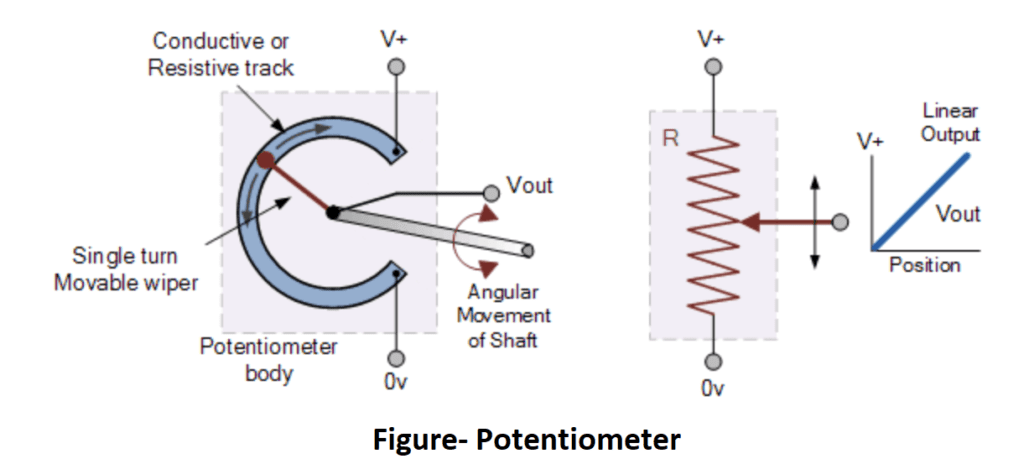
Resistive Position Sensors such as Potentiometer
The most commonly used of all the “Position Sensors”, is the potentiometer since it is inexpensive and easy to use position sensor. It has a wiper contact linked to a mechanical shaft that can be either angular (rotational) or linear (slider type) in its movement, and which causes the resistance value between the wiper/slider and the two end connections to change giving an electrical signal output that has a proportional relationship between the actual wiper position on the resistive track and its resistance value. In other words, resistance is proportional to position.
Inductive Position Sensors such as Linear Variable Differential Transformer (LVDT)
One type of positional sensor that does not suffer from mechanical wear problems is the “Linear Variable Differential Transformer” or LVDT for short. This is an inductive type position sensor which works on the same principle as the AC transformer that is used to measure movement. It is a very accurate device for measuring linear displacement and whose output is proportional to the position of its moveable core. The polarity of the output signal depends upon the direction and displacement of the moving core.
![]()
![]()
![]()
![]()
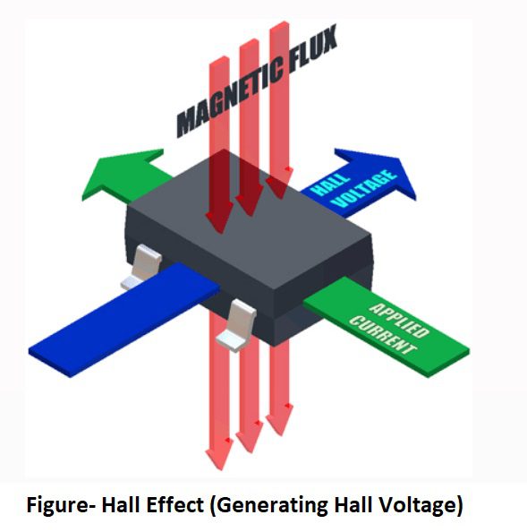
Magnetic positional sensors such as Hall Effect Sensors
Hall Effect sensors are transducers that vary output voltage in response to a magnetic field. Each voltage measurement represents a unique stem position. “When a current-carrying conductor is placed into a magnetic field, a voltage will be generated perpendicular to both the current and the field. This principle is known as the Hall effect.”
Rotary Encoders
Rotary Encoders are another type of position sensor which resemble potentiometers mentioned earlier but are non-contact optical devices used for converting the angular position of a rotating shaft into an analogue or digital data code. In other words, they convert mechanical movement into an electrical signal (preferably digital). There are two basic types of rotary optical encoders, Incremental Encoders and Absolute Position Encoders.
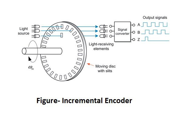
Incremental Encoders, also known as quadrature encoders or relative rotary encoder, are the simplest of the two position sensors. Their output is a series of square wave pulses generated by a photocell arrangement as the coded disk, with evenly spaced transparent and dark lines called segments on its surface, moves or rotates past the light source. The encoder produces a stream of square wave pulses which, when counted, indicates the angular position of the rotating shaft.

Absolute Position Encoders are more complex than quadrature encoders. They provide a unique output code for every single position of rotation indicating both position and direction. Their coded disk consists of multiple concentric “tracks” of light and dark segments. Each track is independent with its own photo detector to simultaneously read a unique coded position value for each angle of movement. The number of tracks on the disk corresponds to the binary “bit”-resolution of the encoder so a 12-bit absolute encoder would have 12 tracks and the same coded value only appears once per revolution.
Read Also:-
Name of parts of control valve
How Instruments classified in Hazardous area?