I to P converter (From Emerson) is also called as “current to pressure” converter or I/P Transducer or Electro-pneumatic Converter which converts an electronic signal (analog output), typically from a control system such as PLC or DCS, to a pneumatic signal used to control a valve. This signal from the control system is typically analog signals in the range of 4mA to 20mA loop. These signals are not compatible with control valves outfitted with pneumatic actuators. Since to operate a control valve, a controlled air supply is provided to actuator via ‘converter’ which receives standard analog output (4 to 20)mA command from controller and convert proportionally in to standard pressure usually between (3 to 15)PSIG, which in turn proportionally controls the opening or closing of a valve.
Principle of Operation
I/P converter operation are based on ‘force balance principle’. To understand its working principle, a block diagram of I/P converter is shown as follows-

The Main units with their function is given below-
- Electronic Circuit with solid state pressure sensor
- Magnetic Actuator
- Pilot Stage
- Booster Stage
A figure showing typical I/P converters are given below-

Input current signal received by the transducer’s electronic circuit and compared to the output pressure signal from the booster stage. A solid‐state pressure sensor is part of the electronic circuit to monitor the booster stage output pressure. The electronic circuit controls the level of current flowing through the actuator coil, located in the pilot/actuator assembly. A change to the level of coil current is made by the electronic circuit when it senses a discrepancy between the pressure measured by the sensor and the pressure required by the input signal. The actuator performs the task of converting electrical energy (current) to motion. Next the pilot stage contains one or two opposed fixed nozzles- the supply nozzle and the receiver nozzle. It also contains the deflector, which is the moving element. The supply nozzle is connected to the supply air and provides a high‐velocity air stream. The receiver nozzle captures the air stream and converts it back to pressure. The receiver nozzle pressure is the output pressure of the pilot stage. The receiver nozzle pressure controls the booster stage, which has a poppet valve design. An increase in receiver nozzle pressure, it positions the valve in the booster stage to produce an increase in the transducer output signal. And a decrease in nozzle pressure, positions the valve to allow air to exhaust i.e. decreasing the output signal. Thus we finally get an output of (3-15) PSI.
An arrangement showing how final output is generated is shown below-
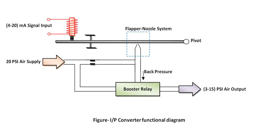
In Electro-pneumatic converter, Analog output from controller is connected as (4-20) mA to its terminal and a pneumatic supply is connected which is to be controlled proportionally. As shown in figure, current output is provided to magnetize coil which move its plunger proportionally i.e. more the current produces more displacement of plunger from which a flapper nozzle system is attached. As displacement increases, back pressure to nozzle also increases which is fed to booster relay and as a result we get final pneumatic output (3 to 15) PSI proportional to applied electric signal (4 to 20) mA.
Read Also:-
I/H Converter
Valve Positioner
Related Search:-