Instrumentation Symbols & Identification
Instrumentation is typically a wide field for study and learning. In industries we are having so many types of Instruments such as Transmitters, Gauges, primary sensors and transducers, monitoring systems, control systems, control valve, relief valves, solenoid etc, Static equipment such as columns, heat exchanges, Vessels, rotary equipments like compressor, turbine, pumps, electric motor etc. These are connected to each other as per a sequential process to finalize the end products from the raw materials. Any operation or sequence of operations involving a change of energy, state, composition, dimension, or other properties is called as process. There are several parameters such as pressure, level, flow, temperature, vibration, speed, and displacement etc. in each and every stage to be controlled as per process requirement. These parameters are called as process variables. Typically, these instruments, equipment, and their interconnection including process variables & their controlling, all can be identified & symbollized. these are termed as Instrumentation symbols and Identification process.
A systematic representation of process can be determined by these different types of instrumentation diagrams-
-
-
ü Process Flow Diagrams (PFDs)
ü Process and Instrument diagrams (P&IDs)
ü Loop diagrams (“loop sheets”)
ü Functional diagrams
-
Process Flow Diagrams (PFDs)
At the highest level, Proper form of diagram to represent the overall view of a process such as interconnections of process, vessels, pipes, and flow paths of process fluids, it termed as Process Flow Diagrams (PFDs). Individual instruments are not represented in a PFD, because the focus of the diagram is the process itself.
Process and Instrument diagrams (P&IDs)
A P&ID shows the layout of all relevant process vessels, pipes, and machinery, but with instruments superimposed on the diagram showing what gets measured and what gets controlled. Here, one can view the flow of the process as well as the flow of information between instruments measuring and controlling the process. A systematic view/ drawing which determines the process having complete details about process, process parameters/ variables, equipments connection diagrams, all type of instruments and equipments with identification are defined as process and instrumentation diagram or P&ID (in sort).
Loop diagrams (“loop sheets”)
At the lowest level, the interconnections of individual instruments, including all the wire numbers, terminal numbers, cable types, instrument calibration ranges, etc. The proper form of diagram for this level of fine detail is called a loop diagram. Here, the process vessels and piping are not represented, because the focus of the diagram is the instruments themselves.
Functional diagrams
Functional diagrams are used for an entirely different purpose: to document the strategy of a control system. In a functional diagram, emphasis is placed on the algorithms used to control a process, as opposed to piping, wiring, or instrument connections. These diagrams are commonly found within the power generation industry, but are sometimes used in other industries as well.
For the representation of such instruments, equipments an standard are followed to define their various types. These are symbolised by specific standard symbols for the identification of different types, are termed as instrumentation symbols. Here Process equipment symbols are not part of this standard, but are included only to illustrate applications of instrumentation symbols. The standard is suitable for use whenever any reference to an instrument or to a control system function is required for the purposes of symbolization and identification. The standard is suitable for use in the chemical, petroleum, power generation, air conditioning, metal refining, and numerous other process industries.
‘American National Standards’ are most widely used and followed by the process industries for the Instrumentation symbols, identification and preparing P&IDs. We will cover all type of symbols, identifications in such format-
ü Instrumentation Identification Letters
ü Instrument line symbols
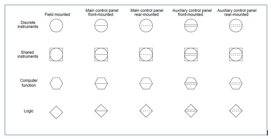
ü General instrument or function symbols (defining mounting)
ü Control valve body symbols, damper symbols
ü Actuator symbols
ü Symbols for self-actuated regulators, valves, and other devices
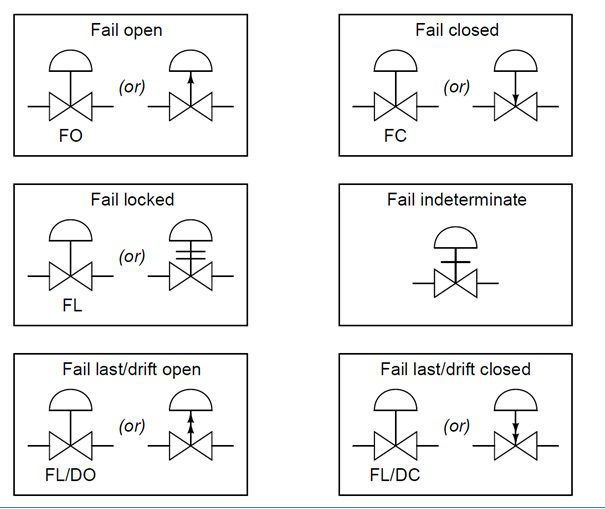
ü Symbols for actuator action in event of actuator power failure
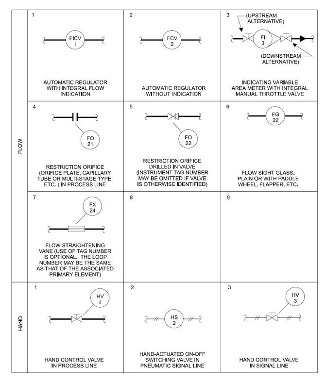
ü Primary element symbols (Level & Flow)
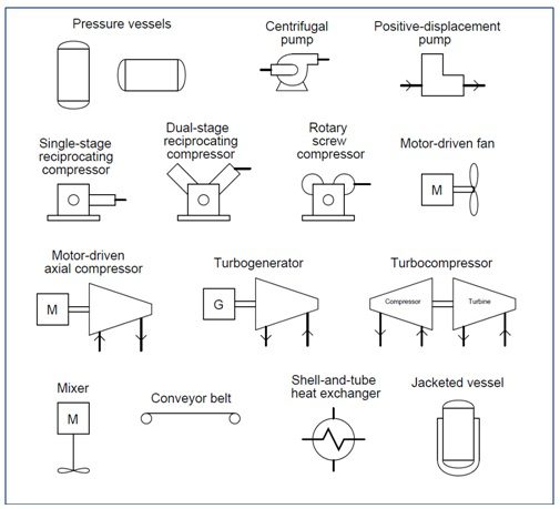
ü Equipments Symbols
Instrumentation Identification Letters

Instrument line symbols

General instrument or function symbols (defining instrument mounting)
Control valve body symbols, damper symbols

Actuator symbols

Symbols for self-actuated regulators, valves, and other devices

Symbols for Valve failure mode
Symbol for Liquid level measurement devices

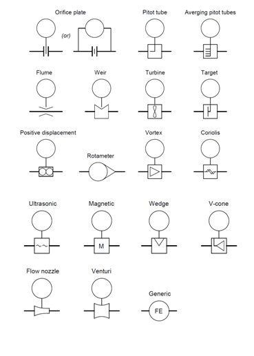
Symbol for Flow measurement devices
Equipments Symbols