Table of Contents
Control Valve performance parameters
Parameter of Control Valve performance parameters is given-
- Dead Band & Back lash
- Actuator-Positioner Design
- Response Time
- Valve trim
- Dead Time
- Gain
- Hysteresis
- Inherent Characteristic
- Shaft Wind-Up
- Valve Capacity (Cv) & (Kv)
- Relative flow capacity
- Fail-Safe Action
- Valve seat leakage Class
Dead Band & Back lash-
Dead band is a general phenomenon where a range or band of controller output (CO) values fails to produce a change in the measured process variable (PV) when the input signal reverses direction. When a load disturbance occurs, the process variable (PV) deviates from the set point, this deviation initiates a corrective action through the controller and back through the process. However, an initial change in controller output can produce no corresponding corrective change in the process variable. Only when the controller output has changed enough to progress through the dead band does a corresponding change in the process variable occur.
According to Fisher-Rosemount (1999), dead band is defined as “the range through which an input signal can be varied, upon reversal of direction, without initiating an observable change in the output signal. Dead band is the name given to a general phenomenon that can apply to any device“. One cause of valve dead band is backlash, whose definition is “the general names given to a form of dead band that results from a temporary discontinuity between the input and output of a device when the input of the device changes direction. Slack or looseness of a mechanical connection is a typical example.”

Actuator-Positioner Design
Actuator and positioner design must be considered together. The combination of these two pieces of equipment greatly affects the static performance (dead band), as well as the dynamic response of the control valve assembly and the overall air consumption of the valve instrumentation. Positioners are used with the majority of control valve applications specified today. Positioners allow for precise positioning accuracy and faster response to process upsets when used with a conventional digital control system. With the increasing emphasis upon economic performance of process control, positioners should be considered for every valve application where process optimization is important.
Response Time
In automatic, regulatory control, the bulk of the signal changes received from the controller are for small changes in position. If a control valve assembly can quickly respond to these small changes, process variability will be improved. Valve response time is measured by a parameter called T63. T63 is the time measured from initiation of the input signal change to when the output reaches 63% of the corresponding change.
Valve trim
Within a control valve body, the specific components performing the work of throttling (or completely shutting off) of fluid flow are collectively referred to as the valve trim. For each major type of control valve, there are usually many variations of trim design.
Dead Time
The time interval (Td) in which no response of the system is detected following a small (usually 0.25% – 5%) step input. It is measured from the time the step input is initiated to the first detectable response of the system being tested. Dead Time can apply to a valve assembly or to the entire process.
Gain
In its most general sense, gain is the ratio of the magnitude of the output change of a given system or device to the magnitude of the input change that caused the output change.
Gain has two components:
static gain and dynamic gain. Static gain is the gain relationship between the input and output and is an indicator of the ease with which the input can initiate a change in the output when the system or device is in a steady-state condition. Sensitivity is sometimes used to mean static gain. Dynamic gain is the gain relationship between the input and output when the system is in a state of movement or flux. Dynamic gain is a function of frequency or rate of change of the input.
Hysteresis
Hysteresis, regarding control valves, is the principle that a control valve is dependent on the prior valve position. A common valve opening may correlate to different flow rates depending on if the valve was opened or closed to get to that position. This shows that the direction a valve is being changed may need to be accounted for in a control system to obtain a desired flow rate. If hysteresis becomes too large, it can cause the control architecture to force a system to oscillate around a desired point.
Inherent Characteristic
The relationship between the flow coefficient and the closure member (disk) travel as it is moved from the closed position to rated travel with constant pressure drop across the valve. Typically these characteristics are plotted on a curve where the horizontal axis is labelled in percent travel and the vertical axis is labelled as percent flow (or Cv).
Shaft Wind-Up
A phenomenon where one end of a valve shaft turns and the other does not is termed as Shaft Wind-up. This typically occurs in rotary-style valves where the actuator is connected to the valve closure member by a relatively long shaft. While seal friction in the valve holds one end of the shaft in place, rotation of the shaft at the actuator end is absorbed by twisting of the shaft until the actuator input transmits enough force to overcome the friction.
Valve Capacity (Cv) & (Kv)
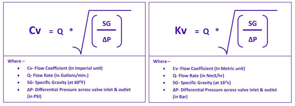
Since a control valve acts like an orifice and the position of the plug decides the area of opening of the orifice. In control valve it is termed as ‘valve throat’. Since the flow rate through an orifice can be expressed in terms of the differential pressure across it & Opening passage. So for proper sizing of a control valve, we are interested in knowing how much flow we can get through the valve for any given opening of the valve and for any given pressure differential. The relationship between pressure drop and flow rate through a valve is conveniently expressed by a flow coefficient (Cv) and (or) Kv.
Here to define flow capacity of a control valve, Cv is used by United States of America based control valves & Kv is expressed by rest of the world. Cv is the flow coefficient in imperial units. & Kv is the flow coefficient in metric units.
The flow coefficient of a control valve (Cv) is a numerical value expressing the number of US Gallons per minute flow of water at 600F the valve will pass with a constant pressure drop of 1 PSI across valve. This rating is usually given for the valve in its wide-open state.
While Kv is defined as a numeric value of Cubic meter per hour (Nm3/hr) of water at a temperature of 160c that will flow through a valve with 1 Bar of pressure drop.
It should be obvious that any control valve must be sized large enough (i.e. possess sufficient maximum Cv capacity) to flow the greatest expected flow rate in any given process installation. A valve that is too small for an application will not be able to pass enough process fluid through it when needed.
The Relationship between Cv and Kv is given as follows-

Relative flow capacity
The flow capacity of a valve (Cv) is a quantitative rating of its ability to pass a fluid flow for a set of given pressure and fluid density conditions. So Not all control valve types exhibit the same Cv coefficients for the same pipe size. For example we have globe valve and butterfly valve with same diameter have different Cv. A globe valve is simply more effective at generating fluid turbulence and therefore dissipating fluid kinetic energy than a butterfly valve of the same pipe size, because the globe valve design forces the fluid to change direction more often and in different ways. So to overcome from this, quantify a particular valve design’s ability to throttle fluid flow is to express this ability as a ratio of flow coefficient (Cv) vs. cross-sectional pipe area. It is termed as Relative Flow Capacity.
Since cross-sectional pipe area is –

we may simplify this ratio by omitting all constants such as π and simply relating Cv factor to the square of pipe diameter (d2). This ratio is called the Relative flow capacity, or Cd.

Fail-Safe Action
It is important to note that each control valve installed in a process system must have a definite fail Position. This is a basic requirement of process for safe shutdown of a process for human safety & also not to affect the process cycle or to minimize the product losses.
A characteristic of a valve and its actuator, which will cause a valve closure member to be fully closed, fully open, or remain in the last position upon loss of actuating energy supply, whichever position is defined as necessary to protect the process. Fail-safe action can involve the use of auxiliary controls connected to the actuator.
- Fail to close (Air to open)
- Fail to open(Air to close)
- Fail to Lock type
Valve seat leakage Class
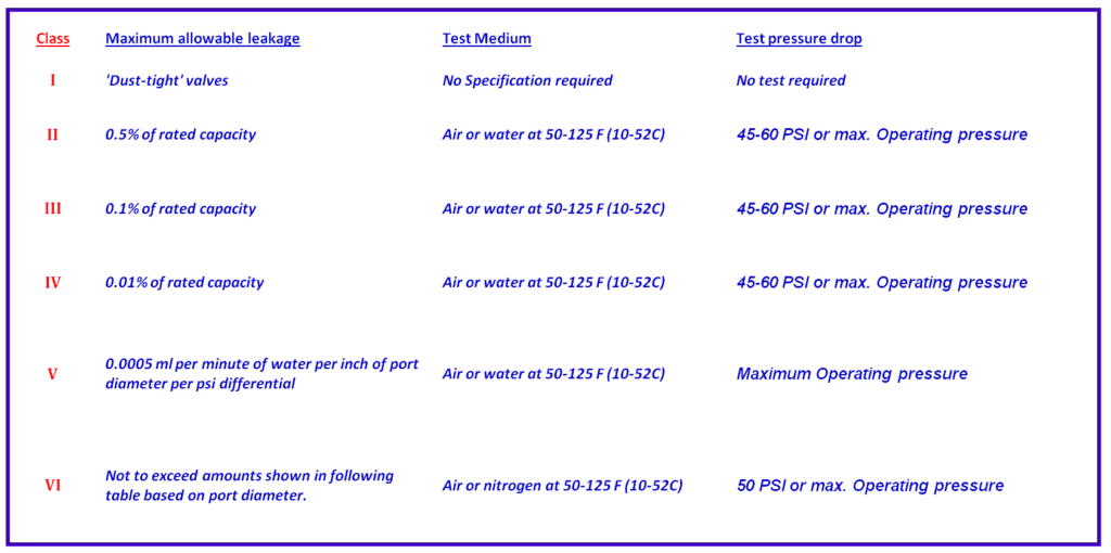
In some process applications, it is important that the control valve should be able to completely stop fluid flow when placed in the “closed” position. The ability to stop fluid completely to pass through it at tight shut off condition is defined by Leakage class. This leakage class is tested using a procedure that the term as ‘bubble-tight shut-off’ under certain pressure. To rate the control valve based on ability too tight shut off Seat leakage tolerances are given using roman numeral designations , the ANSI specifies six different leakage classes, with “leakage” defined in terms of the full open valve capacity , as shown follows-
Read Also:-
Control Valve performance parameters