Table of Contents
Principles of Process control
In present times, process control plays a vital role in industries. We know that in an early stage, it was being controlled manually but today automatic process control has been introduced instead of manual process control.
We can say that process control is an application in manufacturing process industries, satellites, and guided missiles, bio-medical, and engineering.
Process control is to regulate, direct or command a system so that the desired objective is obtained .it is based on a system which is an arrangement of physical components or related in such a way as to regulate, director, command itself to obtain the desired objective.
A process control system can perform the following work.
- It can increase system accuracy.
- It reduces the effect of distortion and non-linearity.
- It reduces the effect of noise and disturbance.
- It reduces the sensitivity to parameter variation.
- It can stabilize an unstable system.
TYPES OF PROCESS CONTROL
There are two types of control system.

Open loop control system
A system in which the output has no effect upon the input quantity is called open-loop control system. Examples are Traffic lights, washing machine, and toaster operation.
Or
Any system which does not automatically correct the variation in its output is called an open loop control system.

Close loop control system
The control system in which the output has an effect upon the input quantity so as to maintain the desired output is called closed-loop control system.
Or
A close-loop control system is one that measures its output and adjusts its input accordingly by using a feedback signal.

In close loop control system, the output or part of the output is feedback to the input for comparison with reference input and an actuating signal is generated .the actauting error signal which is the difference between the input signal and feedback signal is feed to the controller so as to reduce the error and bring the output of the system to a desired value .The close loop control system is also known as feedback control system.
COMPONENT OF A PROCESS CONTROL SYSTEM
There are following basic components that are always present in all control system.
- Sensor and transmitter (to generate a Process variable) also called primary and secondary elements used for the measurement of variables to be controlled and transmission of the measured value to the controller.
- Controller (to generate a manipulated variable) is the brain of the control system and takes decision to maintain the process variables as its desired value (set point).
- Final control element, such as control valve, conveyors, electric motors, variable speed pumps, etc are used to take action for implementing the decision taken by the controller.
- Input: – the applied signal or excitation signal applied to a control system from an external source in order to produce output is called input.
- Error detector:-the error detector is used to reduce the error signal. The error signal is the difference between the input signal and the feedback signal. It is used to reduce the error and bring the output of the system to a desired value
- Feedback Element:-The device which is used to give the feedback signal is called feedback element.
Modes of control
Most industrial processes require that certain variables such as flow, pressure, temperature and level should remain at or near some reference value, called a set point. the device serves to maintain a process variable at the set point is called controller.
Industrial automatic controllers may be classified according to their control action as-
- Two position or on-off controllers
- Proportional(p) controllers
- Integral (I) or reset controllers
- Derivative(D) or rate controllers
- PI controllers
- PD controllers
- PID controllers
01. Two position controller(ON-OFF Control)
In an on-off control action, the output has only two states, fully on or fully off. An on-off controller operates on the manipulated variable only when the measured variable crosses the setpoint. It is a two-position control, merely a switch arranged to be off (or on as required) when the error is positive and on (or off as required) when the error is negative. Ex… Oven & Alarm control. It is a Two-position control used when the controlled process variables need not be maintained at precise values. It is the cheapest type of controller which works best where the system is such that the rates of change of the measured variable with changes of the manipulated variable are slow.

- It will switch the output only when the temperature crosses the set point. For heating control, the output is ON when the temperature is below the set point, and OFF above set point.
Multi step action
A controller action that may initiate more than two positioning of the control with respect to the respective predetermined input values.

02. Proportional control action
A proportional controller continuously adjusts the manipulated variables so that the input to the process is approximately in balanced with the process demand. In proportional control, the output of the controller is proportional to the error.
![]()
![]()
![]()
![]()
Pout: Output of the proportional controller
e(t): Instantaneous process error at time t.
p0: Controller output with zero error.
Kp: Proportional gain


The value of the change in the controller output for a given change in actuating error signal depends upon the proportional band of the instrument which is the range of the controlled variable that corresponds to the full operating range of the final control element .the proportional is also called as correspondence control, droop control, and modulating control.
03. Integral (I) or Reset control action
As long as the measurement remains at the set point, there is no change in the output due to the integral mode in the controller. The output of the controller changes at a rate proportional to the offset. The integral time gives indication of the strength of this action. It is the time taken for integral action to remove the ‘offset’ induced by Proportional Action alone.


In a closed loop, the integral action can be viewed as an extension or amplification of the proportional action; i.e., the controller output continues to respond to error as long as an error is present. In pure integral mode, error can oscillate about zero and can be cyclic. Hence in integral mode is never used alone but combined with the proportional mode, to enjoy the advantages of both modes.
For many processes, the combination of the proportional and the integral actions provides very good control in terms of speed and stability. However, the integral action makes controller tuning a bit more difficult; if set to a value that is too high (too fast), the integral action can cause system instability.
Integral Tuning – To avoid instability, the I Gain value is often initially set fairly low. Through trial and error or other tuning methods, the value of I Gain may be increased to achieve an acceptable balance of responsiveness and stability. In general, a fast process requires a faster integral setting and a slow process requires a slower integral setting.
04. Derivative controller or rate control action
As the PV changes, the controller resists the change. The controllers output is proportional to the rate at which the difference between the measured and desired value changes. The output of the signal of the controller is a function of the rate at which the error is changing. Derivative control action provides the means of obtaining a controller with high sensitivity. An advantage of using derivative control action is that it responds to the rate of change of the actuating error and can produce a significant correction before the magnitude of the actuating error becomes too large.

The proportional mode considers the present states of the process error, and the integral mode looks at its past history, while the derivative mode anticipates its future state and acts on that prediction. Derivative control predicts actuating errors before they have evolved and takes corrective action in advance of that occurrence and tends to increase the stability of the system.

The derivative controller output comes to to be zero, when the error is zero. Hence it is never used alone since faster rate of change of error can cause very large sudden change of controller output this is the reason its gain should be small. it is always used in combination with proportional or proportional plus integral control action.
5. Proportional –integral Controller
In proportional-integral controller, the output is proportional to a linear combination of the input error and time integral of the input error .the mathematical expression for such a composite control is,

Characteristics of PI controllers
- It improves the steady state accuracy.
- It increases the rise time so response becomes slow.
- It filters out the high frequency noise.
- It decreases bandwidth of the system.
- It makes the response more oscillatory.
Application of PI controllers:-
The combination of PI mode removes the offset problems of the proportional mode. Such a mode can be used in the system with frequent or large load changes. But the process must have relatively slow change in the load, to prevent the oscillations
06. Proportional derivative (PD) Controller
The combination of proportional and derivative controller modes gives proportional plus derivative controller. The mathematical expression for the PD composite control is
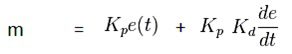
Where Kd = Derivative time
Kp = Proportional gain
M = controller output
Characteristics of PI controllers
- Makes the response fast by reducing the rise time
- For lightly damped system the PD controllers are not very effective
- While implementing a circuit, it may require a relatively large capacitor.
- It reduces overshoot and improves the damping.
- It makes the response stable very fast
- At high frequencies the noise may become dominant.
- It cannot eliminate offset error.
- It improves the bandwidth of the system.
Applications of PD Controllers
The offset error of proportional mode cannot be eliminated . But if the offset error is tolerable, it can be used to handle. It is used in many industrial process control system.
07. Proportional –Integral-Derivative controller
The combination of Proportional-Integral-Derivative (PID) control, also called three mode controllers.

A PID controller produces an output signal consisting of three terms –one proportional to error, another one proportional to integral of error signal and third one proportional to derivative of error signal.
The proportional controller stabilizes the gain but produces a steady state error. The integral controller reduces or eliminates the steady state error. The derivative controller reduces the rate of change of error.
- PID controller has higher stability.
- It has no offset.
- It has reduced overshoot.
With the PID control action; there is no offset, no oscillations with least setting time. So there is improvement in both transient as well as steady state response.
What is cascade control?
Consist of one controller (primary, or master) controlling the variable that is to be kept at a constant value, and a second controller (secondary, or slave) controlling another variable that can cause fluctuations in the first variable. The primary controller positions the set point of the secondary, and it, in turn, manipulates the control valve.

Feedback controllers are used but only one process variable (m) is manipulated. The primary controller maintains the primary variable (c1) at its set point (r1) by automatically adjusting (r2) the set point of the secondary controller. The secondary controller controls the secondary loop responding to both its set point (r2) and the secondary measurement (c2).
Example of cascade control:-
The temperature of the liquid in the vessel is controlled by regulating the steam pressure in the jacket around the vessel.

Controller provides a set point for steam valve or steam-pressure controller.
Such a process involves a long time-constant and a 3-mode controller with long integral time is required. (Single-loop control). This will provide satisfactory control as long as the supply of steam is constant, that is the upstream pressure does not change.
However, if the supply steam is subject to upsets, a different control scheme is needed. The temperature controller will not know the change in heat input (steam pressure) until the temperature of the liquid in the vessel starts to change. Since the time constant of the temperature loop is long, the temperature controller will take a long time to return the process to equilibrium. Therefore it is desirable to correct for the change in heat input before it affects the temperature of the liquid.
Cascade control system will both control the temperature in the vessel and correct for changes in the supply steam pressure. The steam pressure controller (slave) monitors the jacket inlet steam pressure. Any changes in supply pressure will be quickly corrected by re-adjusting the valve because this secondary loop has a fast time constant (short integral time).
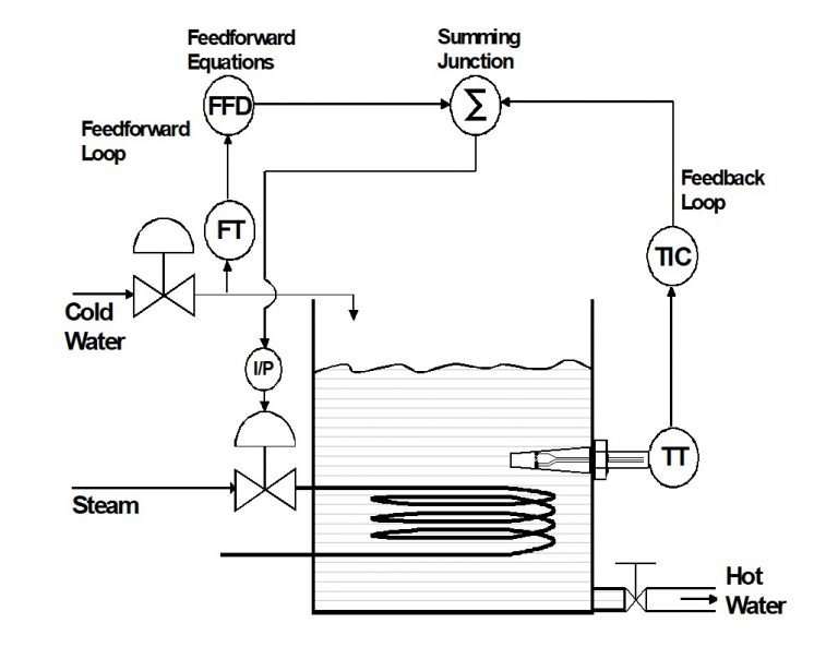
What is feed forward control?
Applies to a system in which a balance between supply and demand is achieved by measuring both demand potential and demand load and using this data to govern supply. It gives a smoother and stable control than feedback control.

- Mathematical Model. The process engineers that are responsible for system design must construct a mathematical model that describes the relationships between the cold water flow rate, the process variable, and the steam flow rate that is required to keep the PV at set point.
- Hardware. A feed forward controller and a summing junction must be included in the system.
- Feedback Loop. In order to ensure good control, a feedback loop, also known as “feedback trim” is typically included in a feed forward system.
Feed forward control is an open loop control. It consists of measurement sensors to measure of disturbances and they feed forward controller in some time in called the load compensator. The sense of the output from feed forward compensator should be in opposition to the disturbance. Practically, there is forward flow of information in the auxiliary open loops without involving the control variable. Hence the disturbance signal which may upset the process is measured and transmitted it the feed forward controller which generates a new manipulated variable and sent to the actuator and the disturbance is taken care of.
What is ratio control?
An uncontrolled flow determines a second flow so that a desired ratio is maintained between them.
“The ratio factor is set by a ratio relay or multiplying unit which would be located between the wild flow transmitter and the flow controller set point. Flow B is controlled in a preset ratio to flow A.”

Flow transmitter A sense the wild flow. The ratio relay multiplies the output (0 to 100%) of the flow transmitter by a manually set factor:
(Flow A) x (Preset factor) = Output of Ratio relay
This output becomes the Set point of the controller that regulates Flow B. At equilibrium, Flow B equals the set point of the controller, or:
(Flow B) = (Flow A) x (Ratio factor) + Constant
Ratio factor = Flow B / Flow A

Flow A – range is 0 to 100gpm & Flow B – range is 0 to 100gpm
The output of Transmitters A & B changes linearly from 0 to 100% as the flow changes from 0 to 100%. The ratio relay has a factor adjustment ranging from 0.3:1 to 3:1.
If the ratio factor is set at 1 (meaning a 1:1 ratio), then Flow B = Flow A
If the ratio factor is set at 2 (meaning a 2:1 ratio), then Flow B = 2 x Flow A
If Flow B – range changed to 0 to 10gpm, a 1:10 ratio is built into the system. In other words, if the ratio factor is 1, then every gallon of A that flows, 0.1 gallon of B will flow.
If transmitters output is proportional to the square of flow, then the ratio will become (2:1)½ or (Ö2:1).
A transmitter with a linear output cannot be used with another with a square root output unless either one is passed thru a converter to obtain a square or square root, as required.
Other Application: Fuel/air ratio control system on combustion equipment, e.g. Boilers.
What is selective control?
The more important condition between two or more candidates is selected. They are used mainly to provide protection to a piece of equipment which could suffer damage as a result of abnormal operating conditions.

In the above example;
Pump speed is controlled to maintain discharge pressure, providing suction pressure does not get below set point.
Each variable has its own controller. The upstream controller is ‘direct acting’. The output signals are fed to a selector unit which selects either the higher or the lower of the two signals and delivers this to the final control element. The scheme is easily extendable to more than two variables.
Another case is;
Rotary compressors are subjected to damage through “surging” if the delivery flow rate is restricted excessively. Controllers are therefore provided for pressure & flow at the compressor delivery. The final control element could be a control valve which bypasses gas around the compressor.