Table of Contents
Valve Positioner (From Emerson) is the most common type control valve accessories used in wide industrial application. A positioner is a motion-control device which is designed to actively compare valve stem position feedback against the control signal, adjusting pressure to the actuator diaphragm or piston until the correct stem position is reached. A typical valve positioners are shown below-

The valve positioner delivers pressurized air to the valve actuator so that the position of the valve stem or shaft corresponds to the set point from the control system. Valve positioners are typically pneumatic or analog I/P and are used when a valve requires throttling action. They require position feedback from the valve stem or shaft and deliver pneumatic pressure to the actuator to open and close the valve.
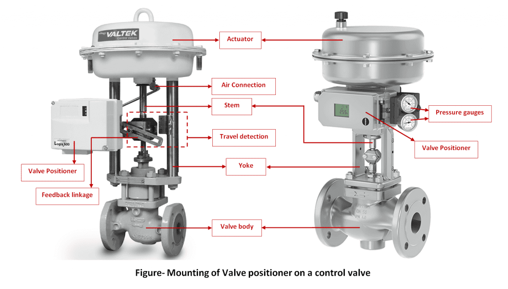
Positioners are generally mounted on the side of the yoke or top of the casing of the pneumatic actuator for linear sliding stem control valves. And for rotary valves, positioners are mounted at/near the end-of-shaft. For either basic design type, “mechanical feedback linkage” connected directly to the valve’s stem which provides feedback to controller. The process controller gives command to the positioner to change position when the position feedback is not matched with the given command. Here feedback linkage reports back to the positioner confirming that a change has occurred and gives a sense of the magnitude of the change in position.
A figure showing how positioner is mounted on control valves is shown below-
Principle of Operation
Since the purpose of a valve positioner is to ensure the mechanical valve’s position matches the command signal at all times. To achieve this, a feedback linkage is provided back to valve positioner. The action of valve positioner depends on how position feedback initiates controlling of pneumatic signal to actuator. The basic principle of valve positioners is based on either Force-balance mechanism or motion-balance mechanism.
Force Balance Principle based valve positioner
A block diagram to understand working of force balance valve positioner is shown as follows-

The control signal for the valve is a (3 to 15) PSI pneumatic signal, coming from either from I/P transducer or from pneumatic controller. This control signal pressure applies an upward force on the force beam, such that the baffle tries to approach the nozzle. Increasing backpressure in the nozzle causes the pneumatic booster relay to output a greater air pressure to the valve actuator, which in turn lifts the valve stem up (opening up the valve). As the valve stem lifts up, the spring connecting the force beam to the valve stem becomes further stretched, applying additional force to the right-hand side of the force beam. When this additional force balances the bellows’ force, the system stabilizes at a new equilibrium.
Like all force-balance systems, the force beam motion is greatly constrained by the balancing forces, such that its motion is negligible for all practical purposes. In the end, equilibrium is achieved by one force balancing another, like two teams of people pulling oppositely on a length of rope, so long as the two teams’ forces remain equal in magnitude and opposite in direction, the rope will not deviate from its original position.
Motion Balance Principle based valve positioner
A block diagram to understand working of motion balance valve positioner is shown as follows-

In motion-balance mechanism, an increasing signal pressure causes the beam to advance toward the nozzle, generating increased nozzle backpressure which then causes the pneumatic amplifying relay to send more air pressure to the valve actuator. As the valve stem lifts up, the upward motion imparted to the right-hand end of the beam counters the beam’s previous advance toward the nozzle. When equilibrium is reached, the beam will be in an angled position with the bellows’ motion balanced by valve stem motion.
Electronic Valve Positioner or Electro-pneumatic Valve positioner
Now days, Electronic positioners are another type of valve positioner which enables electronically comparison of travelled feedback and command signal. A block diagram showing working of electronic positioner is as follows-
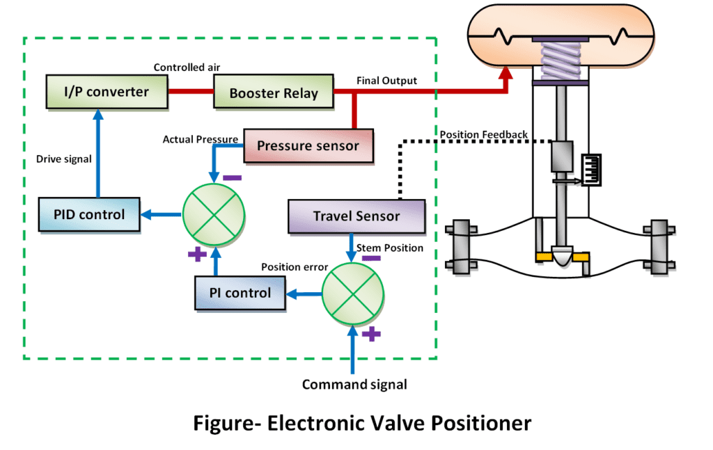
Functioning of a valve positioner is actually a closed-loop control system itself, which applies as much or as little pressure to the actuator in order to achieve the commanded valve stem position at all times. Mechanical valve positioners use levers, cams, and other physical components to achieve this closed-loop control. For example an electronic valve positioner such as the ‘Fisher DVC6200’, use an electronic sensor (hall based sensor) to detect valve stem position, a microprocessor to compare that stem position feedback against the control signal.
Position error = (Position Feedback – Command Signal)
Here Position error determines where the valve’s stem to be positioned. The error signal is fed to controller inside the positioner (PI) calculates how much air pressure at the actuator should be needed to achieve the requested stem position. The next controller (PID) drives the I/P (current-to-pressure) converter as much as necessary to achieve that pressure. If anything causes the valve stem to not be at the commanded position, the two controllers inside the positioner work together to force the valve to its proper position i.e. two control algorithms working together to maintain proper valve position in which one monitoring position feedback and another one controlling pressure applied to the actuator.
Read Also:-
Related Search:-

How to Measure Conductivity?
How to Measure Conductivity?

Tilt type level switch working principle
Tilt type level switch working principle

Valve Positioner
Valve Positioner

How to control boiler drum level
How to control boiler drum level

Moisture Measurement
Moisture Measurement
