Table of Contents
Control Valve Classification
Classification of Control Valve is explained in this article. A control valve is the final control element in a process control. Thus the effectiveness of any control scheme depends heavily on the performance of the control valve. The proper design and fabrication of the valve is very important in order to achieve the desired performance level. Moreover, control valves are of different size and shapes. Various types of control valves can be classified based on their action, valve body, characteristics.
Control Valve classification based on control Actions-
Control Valve classification based on Motion
Control Valve classification based on Design/ application
- Globe Valve
- Ball Valve
- Butterfly Valve
- Gate Valve
- Diaphragm Valve
- Needle Valve
- Plug Valve
- Pinch Valve
- Check Valve
- Self regulating Valve
- Relief Valves
Other special control valve classification-
Control Valve classification based on characteristics
Control Valve classification based on Control Actions
- Direct Acting control valves are those which are directly proportional to the control signal i.e. an increase in control signal will increase the valve opening as well as flow through it. Mostly fail safe action of direct acting valve is signal “Fail to Close” Where as
- Reverse Acting control valves perform reversal action than Direct acting i.e. an increase in control signal will result to move valve towards closing or decrease the valve opening or as well as flow restriction increases. Mostly fail safe action of reverse acting valve is signal “Fail to open”.
Control Valve classification based on Motion
• Linear/ Sliding stem control Valve
Linear Motion control valves are basically control flow through linear movement of flow obstructer. There are different types of linear motion valves such as-
- Sliding Stem control valves
- Multi-turn Rising stem valves
- Axial valvesSliding Stem control valves are widely used for flow control applications. These control valves are operated by transferring motion from actuator to flow obstructer. Examples of Sliding Stem control valves are globe valve, gate valve.
Multi-turn Rising stem valves move the flow obstructer by moving hand wheel which rotates a threaded rod (stem), attached to the flow obstructer Examples of multi-turn valves are gate valves, globe valves, pinch valves, diaphragm valves, and needle valves. Mostly Multi turn valves are hand operated valves not control valves.
Axial valves use pneumatic or electro-magnetic force to slide the flow obstructer along an axis. Some examples of these are coaxial valves, and angle seat valves. These valves are typically fast acting and only used for on/off process applications.
• Rotary stem control Valve
These types of valves rely on the rotary motion of the flow obstructer. In most cases this rotation is limited to 90 degrees (one quarter-turn), however, there are valves that operate using a larger degree of rotation and have more than 2 positions that are used in regular operation. Valves that are truly quarter-turn are completely closed at 0˚ and completely open at 90˚. Examples of quarter-turn valves are ball valves, plug valves, and butterfly valves.
Control Valve classification based on Design/ application
• Globe Valve
Most type of valve used for flow control application is Globe valve. Globe valve is used for starting, stopping, & regulating flow via moving a plug featuring a flat or convex bottom that is lowered onto a horizontal seat situated in the centre of the valve. When a user opens the valve, the plug raises to allow fluid to flow. Globe valves are used for on/off and throttling applications because the disk of the valve can be removed from the flow path completely or it can completely close the flow path. While this type of flow control valve does produce slightly higher pressure drops than straight-through valves like gate, plug, and ball valves, they are applicable in situations where the pressure drop through the valve is not a controlling factor.

There are various types of globe valves used in industrial application such as-
- Stem Guided Globe Valve
- Single Port Guided Globe valve
- Double port Guided Globe valve
- Unbalanced Plug Cage Guided Globe valve
- Balanced Plug Cage Guided Globe valve
- Angle type Globe valve
- 3 way Globe Valve
Stem Guided Globe Valve
When in a glove valve, the valve plug is guided by the stem to maintain alignment with the centre line of the seat. The particular type of globe valve is called a stem guided globe valve.

Single Port Guided Globe valve
When the plug has an unusual shape, projecting into the seat & seat ring acts as a guide for the plug to keep the centre lines of the plug and seat to be aligned always and minimizing guiding stress, It is called as port guided globe valve. If a single set of plug and seat arrangement in valve used for controlling flow through it, then It is called as Single port guided globe valve.
Double port Guided Globe valve
Some globe valves use a pair of plugs (on the same stem) and a matching pair of seats to throttle fluid flow. These are called double-ported globe valves. The purpose of a double-ported globe valve is to minimize the force applied to the stem by process fluid pressure across the plugs. In a double-ported globe valve, there will be two opposed force vectors, one generated at the upper plug and another generated at the lower plug. If the plug areas are approximately equal, then the forces will likewise be approximately equal and therefore nearly cancel. This makes for a control valve that is easier to actuate.
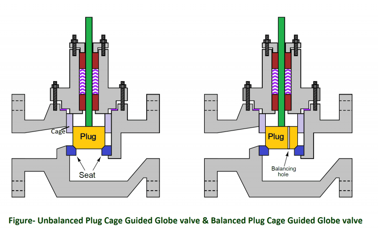
Unbalanced Plug Cage Guided Globe valve
Cage-guided globe valves are available with both unbalanced plug and balanced plug cage. Unbalance plug cage style globe valve do not have a equal & opposite force to balance the plug. So it generate a force equal to the product of the differential pressure across the plug and the plug’s area (F = PA), which may be quite substantial in some applications.
Balanced Plug Cage Guided Globe valve
A balanced plug cage guided globe valve has one or more ports drilled from top to bottom, allowing fluid pressure to equalize on both sides of the plug. This helps minimize the forces acting on the plug which must be overcome by the actuator. Balanced cage guided valves are easy to position, just like double-ported stem-guided and port-guided globe valves.
3 way Globe Valve
Both of them valve will be discussed in special type of valves……………………..Read More about.
Additional features of Globe valves
Recommended for Precise flow regulation, frequent and wide throttling operation & suited to very high pressure drops.
- These valves are available with a wide variety of flow characteristics.
- Suitable for most liquids, vapours, gases, corrosive substances
- General sizes available are 1/2″ to 12″.
- Pressure limitations are relatively high, ranging from 1480 to 1500 psi, dependent on materials of construction, size and temperature.
- Minimum and maximum temperatures are also very broad ranging from -425°F to 1100°F, depending again on the materials of construction.
- Depending on the specific construction and application, the globe valve may comply with ASME class II, III, IV, V or VI shut-off requirements.
- Easily automated and available with positioners, limit switches, and other accessories
Limitations
- Low recovery and relatively low coefficient of flow (Cv).
- High pressure drop, higher pump capacity and system wear
- More expensive than other valves
- The sealing device is a plug that offers limited shut-off capabilities, not always meeting bubble tight requirements.
- These are only well suited for clean fluids only.
• Ball Valve
Ball Valves are commonly used in flow systems across numerous industries due to their low cost, durability, and excellent shutoff capability. Similar to butterfly valves, they are not as effective for flow control applications that require a high degree of accuracy and control. One of the reasons for this is that a ball valve requires a high degree of torque to open and close that prevents an operator from making fine adjustments. There is also a certain amount of “play” between the stem and the ball which can make finding specific flow rates difficult. For flow control applications where a ball valve is possible, such as filling a tank to a reasonable degree of accuracy, a trunnion or v-port ball valve design is usually the best choice.

• Butterfly Valve
A butterfly valve is operated by rotating a disk within the flow area and, due to this design, it does not have linear flow characteristics. This makes these valves less precise than the more common flow control valve types above. For this reason, it can often be dismissed as a flow control valve choice even though it is useful in some applications that do not require a very high degree of accuracy. They are also a very affordable valve option, which makes it worthwhile to consider them in the right applications.

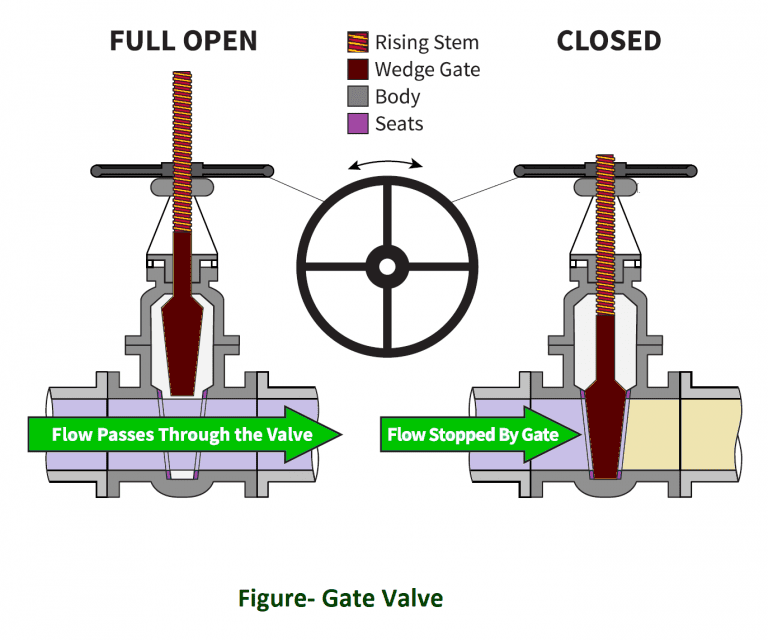
• Gate Valve
Gate valves are used in applications requiring a straight-line flow of fluid with minimum restriction is desired. Gate valves operate when the user rotates the stem in a clockwise to close (CTC) motion or a clockwise to open (CTO) motion. The gate moves up or down on the threaded step when an operator moves the stem, which is why it is a multi-turn valve; the valve must turn several times for it to go from open to closed, and it is the slow operation that prevents water hammer effects. Typical gate valves have no obstruction in the flow path, which results in a minimal loss of pressure. There are two types of gate valves: parallel and wedge-shaped. Parallel gate valves feature a flat gate between two parallel seats. Wedge-shaped gate valves are comprised of two inclined seats and an inclined gate that is just a bit mismatched.
• Diaphragm Valve
Diaphragm Valves are characterized by a flexible disc that contacts a seat at the top of the valve body and forms a seal. The diaphragm is flexible and pressure-responsive; it transmits force to open, close, or control a valve. While diaphragm valves are related to pinch valves, they use an elastomeric diaphragm rather than an elastomeric liner in the valve body. The elastomeric diaphragm is attached to a compressor and separates the flow stream from the closure element. Diaphragm valves are ideal for handling corrosive, erosive, and dirty services.
There are many advantages to using diaphragm valves: they are extremely clean, feature a leak-proof seal, have a tight shut-off, are easy to maintain, and reduce leakage to the environment. Diaphragm valves also may be repaired without interrupting a pipeline. On the other hand, the disadvantages of using diaphragm valves include only being able to use them in moderate temperatures of -60 to 450 degrees Fahrenheit and in moderate pressures of approximately 300psi. Diaphragm valves cannot be used in multi-turn operations and do not have industry standard face-to-face dimensions. Also, the body of a diaphragm valve must be made of corrosive-resistant materials.

• Needle Valve
Needle Valves are volume control valves that restrict flow in small lines. Fluid moving through the valve turns 90 degrees and flows through an orifice that serves as the seat for a cone-shape-tipped rod. The orifice size changes when the user positions the cone in relation to the seat. Needle valves are similar to globe valves in that they share a few design features and have similar benefits. Needle valves can provide positive shutoff in order to allow gauges and other measurement instruments to be installed or removed safely. That’s also why needle valves may be used in a range of industries. It is the needle valve’s finely-threaded valve stem that gives it a significant mechanical advantage by allowing operators to seal it using only minimal force. One disadvantage of needle valves, however, is that the visual inspection alone is not enough to determine whether a needle valve is open or closed.

• Plug Valve
Plug valve. Comes in a variety of configurations and are operated by rotating a cylindrical or cone-shaped plug within the valve body to regulate the flow through a hollow area of the plug. For flow control applications the most common design is an eccentric plug valve, which uses a half plug to create a higher seating force with minimal friction as it is opened and closed. This has the advantage of greater shut off capability which is ideal for flow control situations.

• Pinch Valve
A cost-effective flow control valve, pinch valves are ideal for applications of slurries or liquids containing significant amounts of suspended solids. Pinch valves seal using one or more flexible elements like rubber tubes that become pinched to turn off the flow. These rubber sleeves are the valve’s only wetted part, and their flexibility allows pinch valves to close tightly around entrapped solids. Air or hydraulic pressure is placed directly on the elastomer sleeve to actuate pinch valves. A pinch valve’s body acts as a built-in actuator, which eliminates expensive hydraulic, pneumatic, or electric operators and results in the cost-effectiveness of this type of flow control valve.

• Self regulating Valve
Self regulating valves as name suggests operates valve based on pre-defined set points. It does not require any external signal to control process parameter. Self-operated regulators are available for temperature, pressure, flow, and differential pressure control. Self-operated regulators take over complete process controlling required in a control loop i.e. a measuring sensor, set point & final control element all in one. They are suitable for all those applications where deviations of the controlled variable from the adjusted set point are acceptable and the set point remains constant over a long time. Self regulating valves act as a proportional controller to regulate the pressure. Process medium is used for actuating or throttling valve as controlling signal/ pressure (until desired set point achieved). A schematic diagram showing self regulating valve is shown as follows-
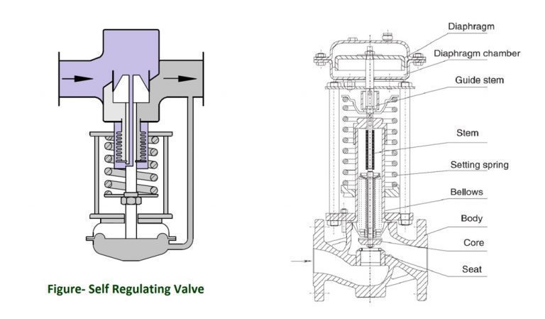
As shown in figure, a Self regulating valve is composed of a valve, actuator & a spring mechanism for operating pressure setting. These valves can be used for upstream or downstream pressure control. When it is used for upstream pressure control, it is called as back pressure control valve & when it is used for downstream pressure control, it is termed as pressure reducing valve.
• Check Valve
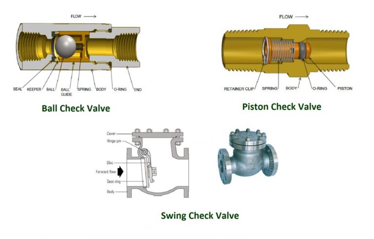
Check Valve is referred sometimes as a non-return valve. The check valve prevents back-flow in the piping by constantly keeping fluid flowing in one direction. Check valves are automatic valves that open with forward flow and close against reverse flow. Check valves operates in such manner that it avoids the formation of an excessively high surge pressure as result of the valve closing & Rapid fluctuating movements of the valve closure member. Some piston/disc check valves are spring loaded for fast operation, but minimum cracking pressure should be specified. Vertical downwards flow requires a spring loaded check valve.
Swing Check Valves: – Swing & Wafer checks cease reverse flow with a flap that swings onto a seat. Use swing checks only for forward flow that is horizontal or vertical upward.
Piston Check Valves: – Piston & Spring checks cease reverse flow with a spring loaded plunger.
Ball Check Valves:– Ball checks have a ball that slides into a hole as forward flow slows. Consider a ball check for semi-solids such as pulp or effluent.
Tilting Disc Check Valves: – Tilting Disc check valves are similar to Swing check valves but in most installations, slamming is minimised upon reversal of flow so noise and vibration are reduced.
• Relief Valves
Relief Valves are safety devices that are designed to protect a pressurized vessel or system during an overpressure event. An overpressure event refers to any condition which would cause pressure in a vessel or system to increase beyond the specified design pressure or maximum allowable working pressure. The primary purpose of a pressure Relief Valve is protection of life and property by venting fluid from an over pressurized vessel. When a process system/ plant is designed, it is ensured that the system should be completely protected against over pressure situation to do so there are pressure measuring instruments such as pressure transmitter, temperature measuring instruments etc., control valves, controllers & interlocks to protect the system. Relief valves works when all controls lost due to various reasons and system is uncontrollable to pressure & reached at dangerous level. Relief valves & rupture disc are treated as final stage of protecting equipments/ system. Relief valves blow out the system over pressure fluid at a predetermined set pressure, flow a rated capacity at a specified over pressure, and close when the system pressure has returned to a safe level.
A Relief Valve is a pressure relief device actuated by inlet static pressure having a gradual lift generally proportional to the increase in pressure over opening pressure. It may be provided with enclosed spring housing suitable for closed discharge system application and is primarily used for liquid service. A safety Relief Valve is characterized by rapid opening or pop action, or by opening in proportion to the increase in pressure over the opening pressure, depending on the application and may be used either for liquid or compressible fluid.

Conventional safety relief valve
A conventional safety Relief Valve is a pressure Relief Valve which has its spring housing vented to the discharge side of the Valve. The operational characteristics (opening pressure, closing pressure, and relieving capacity) are directly affected by changes of the back pressure on the Valve.
Balanced safety relief valve
A balanced safety Relief Valve is a pressure Relief Valve which incorporates means of minimizing the effect of back pressure on the operational characteristics (opening pressure, closing pressure, and relieving capacity).
Pilot-operated pressure relief valve
A pilot operated pressure Relief Valve is a pressure Relief Valve in which the major relieving device is combined with and is controlled by a self-actuated auxiliary pressure Relief Valve.
Power-actuated pressure relief valve
A power actuated pressure Relief Valve is a pressure Relief Valve in which the major relieving device is combined with and controlled by a device requiring an external source of energy.
Temperature-actuated pressure relief valve
A temperature-actuated pressure Relief Valve is a pressure Relief Valve which may be actuated by external or internal temperature or by pressure on the inlet side.
Vacuum relief valve
A vacuum Relief Valve is a pressure relief device designed to admit fluid to prevent an excessive internal vacuum; it is designed to reclose and prevent further flow of fluid after normal conditions have been restored.
Other special control valve classification-
• Three Way Valve
Most of the control valves which are used to control flow, pressure are 2 way valve or two port valves. But in some cases we need to mix two fluids in one or need to divert / bypass the fluid, for this purpose 3 way valves are used having 3 ports for mixing or diverting service as described below-
3 -Way Mixing Valve
This type of valve would be used for blending of two fluids with the associated ratio control of the mix. A three-port valve with two inlet flows and one common outlet flow is defined as a mixing valve, and it provides a variable temperature outlet at a constant flow rate. A three-port motorized valve can be used to MIX, in varying proportions, two flows of different temperatures while maintaining a constant rate of flow in the common outlet port. A mixing valve is used normally for radiator circuits.

3-Way diverter Valve
Diverting valves can be used for switching or for bypass operations. The relative split provides the required controlled flow with one outlet, while allowing a constant flow through the system with the other outlet.
A three-port valve may also be used to divert a common flow in varying proportions. The valve will have one inlet and two outlets and provides a constant temperature and variable flow rate. Mostly diversion of flow is required in temperature maintaining circuits. A diverting valve is used normally for circuits with convective heat transfer such as; heat exchangers, primary coil in indirect cylinder, heater battery, cooling coil etc.
• Angle Valves
Angle valves are designed for the specific purposes & specific process conditions. There are several type of pattern for angle valves-
L Pattern Angle Valve
The Angle pattern globe valve is a modified version of conventional Pattern valve with inlet and outlet at right angles (90 Degree). When fitted at a change in piping direction, this valve eliminates a bend and has the advantage of smaller pressure drop than a conventional pattern globe valve. Angle valves have the same features of stem, disc and seat ring design as the globe valve. The fundamental difference between the two is that the fluid flow through the angle valve makes a 90° turn. These valves offer less resistance to flow than a globe valve with an elbow which it would replace. An angle valve reduces the number joints in a line, in addition to saving installation time. They are also used in applications that have periods of pulsating flow because of their capability to handle the slugging effect of this type of flow. The Angle valve has little restriction on the out flow, so if flashing or cavitation occurs then it tends to do so further downstream from the valve. This saves not only on the maintenance life of the valve, but also minimises any degradation in valve performance.

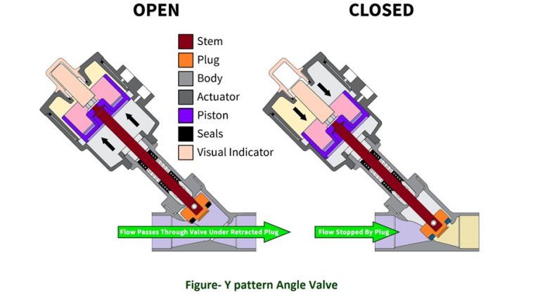
Y Pattern Angle valves
Y-pattern angle valve body is an alternative for the high pressure drop in which Seat and stem are angled at approximately 45 degrees. a straighter flow path at full opening and offer the least resistance to flow. so the pressure loss through the valve is also reduced accordingly. These valves can be cracked open for long periods without severe erosion. They are extensively used for throttling during seasonal or start up operations. These are mostly used to contain solid particles or viscosity of the fluid.
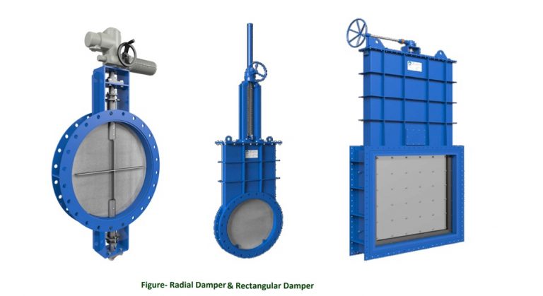
• Dampers and louvers
Dampers are basically high volume flow regulating/ throttling valves generally operates at low pressure which are used to stop & regulate the flow inside a furnace/ boiler draft, duct, chimney or other large area air/ gas handling equipments. Dampers consist of a larger area plate or butterfly wafer, or a set of vanes attached each other and linked with a hand wheel and or piston actuator to operate/ throttling application. These dampers are basically a special type of Gate valve or a butterfly valve (of large area flow control application). Common designs of a damper are rectangular and radial type as shown in figure-
Dampers can be operated by either manually or pneumatic piston actuators or electrically using motorised control. These dampers mostly used in such application as –
- HVAC (heating, ventilation & air conditioning system)
- Furnace draft pressure control,
- Flue gas flow control & diversion
- Exhaust gas control on combustion process
- Gas turbine-exhaust gas control
- Exhaust gas control on chimneys etc.
• Guide Vanes
Guide Vanes are special type of valves designed for controlling & distributing uniformly flow in rotating machinery such as compressor, turbine and a pump by producing vortex or some form of forced-vortex free fluid velocity distribution. The main function of guide vanes is to adjust the turbine or compressor load. The guide vanes are mostly located before the impeller eye & guide the flow of gas efficiently into the eye of the impeller. The guide vanes consist of number of blades/ vanes that can be adjusted simultaneously in order to increase or reduce the flow rate through the turbine/ compressor. A Guide vane is shown in figure-

Control Valve classification based on characteristics
The control valve acts like an orifice and the position of the plug decides the area of opening of the orifice. In control valve it is termed as ‘valve throat’. Since the flow rate through an orifice can be expressed in terms of the upstream and downstream static pressure heads & Opening passage. So under same static head pressure maintained, we can say that shape of the plug decides how the flow rate changes with the stem movement, or lift. In this way, the control valves can be classified in terms of their relationship between valve opening (% Lift) and flow rate (under constant pressure condition) characteristics, and three types of control valves are normally in use. They are:

• Quick Opening
A quick opening valve plug produces a large increase in flow for a small initial change in stem travel. Near maximum flow is reached at a relatively low percentage of maximum stem lift.
• Linear characteristics
An inherent flow characteristic that can be represented by a straight line on a rectangular plot of flow coefficient (Cv) versus rated travel. Therefore equal increments of travel provide equal increments of flow coefficient, Cv.
• Equal Percent characteristics
The equal percentage valve plug produces the same percentage change in flow per fixed increment of valve stroke at any location on its characteristic curve.
Different valve characterizations may be achieved by re-shaping the valve trim. For instance, the plug profiles of a single-ported, stem-guided globe valve may be modified to achieve the common quick-opening, linear, and equal-percentage characteristics.

Cage-guided globe valve trim characteristic is a function of port shape. As the plug rises up, the amount of port area uncovered determines the shape of the characteristic graph.

Read Also:-
Related Search:-

Actuators
Actuators

7-Segment LED Display
7-Segment LED Display

Touch Screen Display
Touch Screen Display

Quick Exhaust Valve
Quick Exhaust Valve

Flow switches
Flow switches
