Table of Contents
Dynamic characteristics of a measuring instrument describe its behavior between the time a measured quantity changes value and the time when the instrument output attains a steady value in response. As with static characteristics, any values for dynamic characteristics quoted in instrument data sheets only apply when the instrument is used under specified environmental conditions. Outside these calibration conditions, some variation in the dynamic parameters can be expected. The set of criteria which defines how rapidly response of an instrument or characteristics changes with time is called dynamic characteristics of an Instrument.
Various dynamic characteristics are described below-
- Signal Response
- Dynamic Performance
- Response time
- speed of response
- Measuring Lag
- Fidelity
- Dynamic Error
Signal Response
Signal response is defined as the output response of an instrument when an input test signal is applied to it. There are two type of response
- Static Response
- Dynamic Response
When an input is applied to an instrument or a measurement system, the instrument or the system cannot take up immediately its final steady state position. It goes through a transient state and then after steady state. The transient state response of instrument is called as dynamic response of instrument, whereas steady state analysis determines static response. A figure showing static & dynamic part of response as transient & steady state response is given as follows-
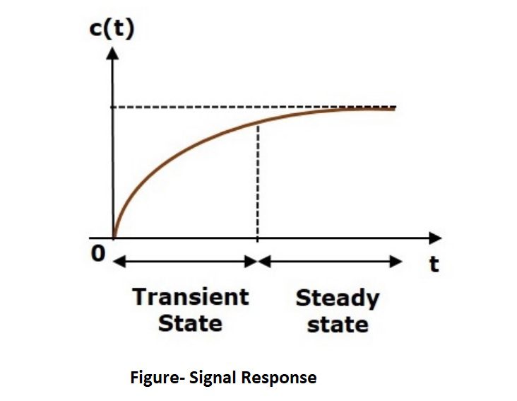
Here, both the transient and the steady states are indicated in the figure. The responses corresponding to these states are known as transient and steady state responses.
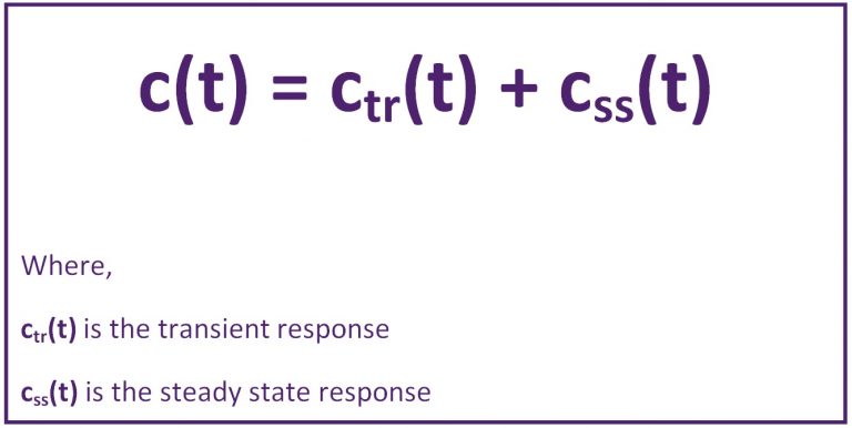
Mathematically, we can write the time response c(t) as-
Dynamic Performance
This is a measure of how well a system responds to a changing input. The dynamic specification can be defined by applying one of or more standard input signals and then examining the resultant output. Various standard test inputs are as follows (Click on signal type to know more)-
- Step Signal
- Ramp Signal
- Sine Wave signal
- Parabolic Signal
- Impulse input

To understand the instrument/ system response, we can examine these test signals response under two analysis methods as follows (Click on the method to read more)-
- Time Domain Analysis
- Frequency Domain Analysis
If the output of control system for an input varies with respect to time, then it is called the time response of the control system whereas the frequency response performance refers to the performance of the system subject to sinusoidal input of varying frequency. Here Sine wave signal is used for frequency domain analysis where except sine wave; all are used for time domain analysis.
Response time
Response Time is defined as the time required by instrument or system to settle to its final steady position after the application of the input. So we can say response time determines required time to produce output when input is applied to the instrument.
Speed of response
Speed of Response is defined as the rapidity with which an instrument or measurement system responds to changes in measured quantity. So we can say that speed of response determines speed at which the instrument responds whenever there is any change in the quantity to be measured is called speed of response. It indicates how fast the instrument is.
Measuring Lag
Measuring lag is defined as the delay in the response of an instrument to a change in the measured quantity/ input signal, since an instrument does not react to a change in input immediately. In the high speed measurement systems, as in dynamic measurements, it becomes essential that the time lag be reduced to minimum.
Measuring lag is of two types-
- Retardation type
- Time delay
In Retardation type of measuring lag, the response begins immediately after a change in measured quantity has occurred, where as in time delay type of measuring lag, the response of the measurement system begins after a dead zone after the application of the input.
Fidelity
Fidelity of a system is defined as the ability of the system to reproduce the output in the same form as the input. It is the degree to which a measurement system indicates changes in the measured quantity without any dynamic error. Supposing if a linearly varying quantity is applied to a system and if the output is also a linearly varying quantity the system is said to have 100 percent fidelity. Ideally a system should have 100 percent fidelity and the output should appear in the same form as that of input and there is no distortion produced in the signal by the system. In the definition of fidelity any time lag or phase difference between output and input is not included.
“It is defined as the degree to which a measuring instrument is capable of faithfully reproducing the changes in input, without any dynamic error.”
Dynamic Error
The dynamic error is the difference between the true value of the quantity changing with time and the value indicated by the instrument if no static error is assumed. However, the total dynamic error of the instrument is the combination of its fidelity and the time lag or phase difference between input and output of the system.
Read Also:-
Related Search:-

Displacer type level switch working principle
Displacer type level switch working principle

Control Valve Classification
Control Valve Classification

Paramagnetic Type Oxygen analyzer
Paramagnetic Type Oxygen analyzer

Quick Exhaust Valve
Quick Exhaust Valve

Paddle level switch working principle
Paddle level switch working principle
