Table of Contents
What is LVDT ?
With the help of the mutual induction principle, a linear variable differential transformer (LVDT) transforms linear displacement into an electrical signal as an absolute measurement tool. It offers extremely high resolution in a tool suitable for a variety of applications and situations, and its design and use are reasonably straightforward.
LVDT Stands for | LVDT full form
Linear Variable Differential Transformer is known by the abbreviation LVDT. It is the inductive transducer that transforms linear motion into electrical signals most frequently utilised.
LVDT working principle
Linear Variable Differential Transformer is known by the abbreviation LVDT. It is a significant variety of inductive transducer; inductive transducers are those that operate according to the basic tenets of the transduction process. The Linear Variable Displacement Transducer (LVDT) is another name for LVDTs, which are also known as inductive transducers that measure linear displacement from the polarity and magnitude of the net induced electromotive force (emf). LVDT, in its simplest form, is a position sensor that can detect and translate linear motion or vibrations into electrical signals or a variable electrical current in the circuit.
 According to Faraday’s law of electromagnetic induction, which states that “the net induced emf in the circuit is directly proportional to the rate of change of magnetic flux across the circuit, and the magnetic flux of the coil wounded with wires can be changed by moving a bar magnet through the coil,” the operation of an LVDT is based on this principle.
How does an LVDT work ?
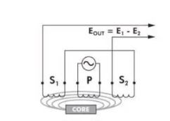
When the LVDT’s primary winding is linked to the AC power source, an alternating magnetic field is created there, which induces an emf in the secondary windings. Assume that the secondary windings S1 and S2 have induced voltages of E1 and E2, respectively. Now, in accordance with Faraday’s Law, the magnitude of the induced emfs, E1 and E2, as well as the rate of change of the magnetic flux, dØ/dt, are directly proportional to each other. Therefore, if the value of “dt” is low (dØ/dt ∝ E1 and E2), the induced emf in the secondary windings will be greater, and the low value of “dt” means that the soft iron core present inside the LVDT is moving quicker. If the core moves more quickly inside the LVDT, a significant amount of emf will consequently be generated in the secondary windings S1 and S2.
The secondary windings S1 and S2 are both linked in series but with opposing phases; as a result of this phase opposition connection, the circuit’s overall output voltage (Eo) is provided by,
E0= E1 -E2
LVDT construction
Similar to a transformer, an LVDT has one main winding, designated P, and two secondary windings, designated S1 and S2. The primary and secondary windings are wound on a former, which is a hollow cylindrical structure. The former is often constructed from glass-reinforced polymer that has been wrapped in a porous substance and covered with cylindrical steel. The cylindrical former’s primary winding is located in the centre, and secondary windings are equally spaced from the centre on either side of the primary winding. Both secondary windings have the same number of turns and are connected to one another in series opposition, meaning that they are wound in different directions yet are connected to one another. The induced EMF in both secondary coils will be in opposition to one another due to the series-opposed connection. A steady source of the AC power supply, whose frequency spans from 50 Hz to 20 kHz, is linked to the primary winding. Throughout the linear distance measurement procedure, the entire coil assembly is stationary. The LVDT’s movable component is a separate arm constructed of a magnetic substance. It typically has a soft iron core that is laminated to lessen eddy current losses. The core is free to move inside the hollow coil (former), and the core is connected by a non-magnetic rod to the object whose movement needs to be recorded. In order to prevent any physical contact between them(coil and core) and allow the coil to travel freely inside the former, the hollow former has a wider radial diameter than the core.


 Characteristics of LVDT
Let’s discuss about the three various scenarios according to the position of the movable core since the net emf induced in the circuit depends on its position.
Core at the Null Position
The rate of change of magnetic flux in both secondary windings will be the same since both secondary windings have an equal number of turns and are positioned at an equal distance from the main winding, or at the normal position when the core is put in the centre. This suggests that the induced emfs E1 and E2, which are present in the secondary windings S1 and S2, will be equal, or E1=E2. As a result, at the core’s normal position, the net induced emf (Eo) in the circuit is zero (E1-E2=0). The “Null Position” of the LVDT is the typical position of the soft iron core at which the net induced emf is zero.

Core at left side of null position
A differential AC voltage will develop across the output terminal of the secondary coils when the core is moved away from the null state, causing an electromagnetic imbalance between the secondary windings. The magnetic flux associated with the secondary coil S1 will grow to be greater than the magnetic flux associated with the coil S2, or the induced emf in coil S1 will be greater than the induced emf in coil S2, if the core is shifted to the left from the null point.
Consequently, the LVDT’s output voltage (E0) is provided by,
E0= E1 – E2 = Postive (E1 > E2)
As a result, it may be inferred that the LVDT’s overall output voltage is positive and in-phase with the primary voltage.
Core at right side of null position
The magnetic flux associated with winding S2 will be greater than that of winding S1 if the core is shifted away from the null position to the right. As a result, the induced emf in winding S2 will be greater than the induced emf in winding S1.
As a result, the LVDT’s tool output voltage (E0) is given by,
Eo = E1 – E2 = Negative (E2 > E1)
This suggests that the LVDT’s total output voltage is negative, or out of phase(Φ=1800 ) with the primary voltage.

From the three situations stated above, it can be inferred that the output voltage is exactly proportional to the body displacement, i.e., the greater the body displacement, the greater the LVDT output voltage. Therefore, the net output voltage measured across the LVDT’s output terminal can be used to determine the direction of movement of the body attached to the core of the device. If the output voltage of the LVDT is positive, one can conclude that the body is moving away from the null location in a leftward direction, and if the output voltage of the LVDT is negative, one can conclude that the body is moving away from the null position in a rightward manner.
The output voltage of the LVDT, however, will be zero if the core is removed from the hollow structure. Up to a 5 mm displacement from the null position, either to the left or to the right, the output voltage is seen to increase linearly, but after that point, it deviates from linear behaviour. The accompanying graph, which depicts the fluctuations in output voltage with respect to body displacement, can help us understand the linear range and linearity mistake.
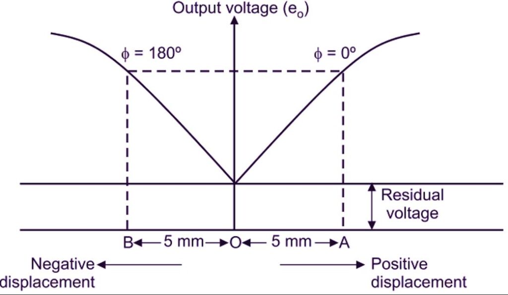
The linear variable differential transducer’s transfer function is depicted in the graph up above. The magnitude of the LVDT’s output voltage is shown by the y-axis, while the body’s displacement is represented by the x-axis. The output voltage should, in theory, be zero when the displacement is zero, but because the soft iron core’s residual magnetism produces a little output voltage even when the core is in the null position, this small output value is referred to as the residual voltage of an LVDT. The output voltage grows linearly with regard to core displacement as the core is moved away from the null position to the right or left until a certain value, at which point a non-linear increase in output voltage is noticed.
Linear Range of LVDT
As shown in the above picture The linear range of the LVDT is the range up to which the linear transfer function is observed. The LVDT only exhibits a linear increase in output voltage for a small range of core displacement. Let’s now examine the reason for the output voltage’s non-linear behaviour after a specific range of displacement. The full-scale displacement is the greatest distance that the core can move from the null position up to where the linear transfer function can be seen. After full-scale displacement, the magnetic flux associated with the core due to the primary winding P decreases as the core is moved further, which finally causes the voltage across the secondary windings S1 and S2 to decrease.
Linearity error in LVDT
In the output versus displacement graph, the linearity error is the largest departure of the output voltage from the predicted straight line. The output voltage fluctuation with regard to displacement in the linear range does not result in a completely straight line, as can be seen from the graph. The saturation of the soft iron core, which causes the third harmonic component even when the core is at the null position, is the cause of the nonlinear curve even in the linear range. The low-output filter at the LVDT’s output terminal can be used to suppress the harmonic components.
Sensitivity of LVDT | Transference ratio of the LVDT
The relationship between the LVDT’s output voltage and core displacement is described by the sensitivity of the device. It is also referred to as the LVDT transference ratio. When the primary AC source is maintained at a specific voltage (3 Vrms) and the core is moved by the full-scale displacement from the null position, the sensitivity of the LVDT is determined. Next, the voltage across the windings S1 and S2 is measured to determine the LVDT’s net output voltage. The collected numbers are then used to modify the following equation to determine the LVDT’s sensitivity.
Sensitivity = V output / (Vprimary × Core Displacement)
V output / (Vprimary Core Displacement) is the formula for sensitivity.
It is written as mV/V/mm or mV/V/in, which stands for millivolt output per volt of excitation per core displacement in millimetres or inches.
Applications of LVDT
When an object is submerged in non-corrosive, non-conductive fluids, hydraulics uses it to check for leaks or other damage. Robotic manipulators also use LVDT sensors.
It is employed in the aerospace sector to keep an eye on numerous mechanisms, including pilot and flight control. The moving core is attached to the moving parts, such as landing gears, and a variety of mini-positon transducers are mounted at the fixed points. Depending on the sensitivity of the LVDT and the mounting system, different electrical output signals supply the angles, lengths, motion, and rate of the moving when the landing gears are moved.
If utilised as a secondary transducer, the LVDT can be used to monitor physical properties such as force, pressure, and weight in addition to displacement. For instance, a Bourdon tube can be used as the primary transducer to measure pressure by converting it to linear displacement. The linear displacement is then converted by an LVDT into voltage or electrical signals, allowing us to obtain the pressure reading.
Additionally, it is employed in the creation of pills in the medical industry. This is accomplished via a computer-controlled hybrid mechanism that properly measures the weight and thickness of the tablets while minimising human error. It consists of primary and secondary winding transducers.
In civil engineering, LVDT is used to evaluate things like spring tensions, weight, and displacement as well as to test the durability of different soil samples and rocks that utilised to build buildings or bridges.
By observing the waveform at the LVDT output terminal, they can also be used to test the quality of flat display panels.
Advantages of LVDT
- LVDTs are constructed using high-quality components and methods that are easily resistant to rust, pressure, and extreme temperatures. Even at temperatures higher than its operating temperature, the LVDT’s null point often remains constant.
- Since there is no friction during LVDT operation, the core’s location can be adjusted quickly, leading to dynamic reactions from the LVDT. The bulk of the core is the single factor thought to restrict the LVDT’s ability to respond dynamically.
- The absolute value is provided by the LVDT. It implies that in the event of an unexpected power outage, the LVDT does not lose its location data. If the measurement is redone, the output value stays the same as it was before to the power outage.
- As there is no direct contact between the moving core and the fixed coil structure, LVDT is a frictionless device (former). As a result of friction-related wear and tear being reduced, the device is less likely to sustain damage. As a result, the mechanical life of an LVDT is significantly longer than that of other devices that experience friction during operation.
- It can be used to calculate an object’s displacement that spans from a few centimetres to a few millimetres. In laboratories and for industrial uses, modern LVDTs that can measure displacement over wide ranges (±100μm to ±25 cm) are frequently utilised.
- They typically use less than 1 W of electricity and exhibit less hysteresis loss, which improves their reliability.
- In spite of their tiny size and lightweight nature, LVDT are capable of withstanding mechanical shocks and vibrations. Because of their small size and lightweight nature, LVDT may be readily managed and aligned to meet requirements.
- Since there is no direct connection between the coil and core of the LVDT and instead they are magnetically connected, they can be removed from one another. This can be accomplished by placing a non-magnetic tube between the core and the former; at this point, pressurised fluid is supplied to the tube that has been placed there. Typically, this assembly is used in hydraulics for a variety of measures.
- Due to its strong output signal and sensitivity to even tiny displacements, LVDT does not require the use of an amplifier to amplify the signals.
Disadvantages of LVDT | Limitations of LVDT
- The primary drawback of the LVDt is the need for an auxiliary circuit to handle the stray magnetic field it generates across the electric circuit. The LVDT’s inductive transducer mechanism produces the stray magnetic field.
- Due to unwanted vibrations or temperature fluctuations in the device, the LVDT’s performance may lag.
- Since the LVDT produces AC output, a demodulator is needed to produce DC output.
- Due to the mass of the movable core or the frequency of the applied primary voltage, the LVDT’s quick dynamic responses may be restricted.
We have tried to cover almost all the topics related to LVDT in this article. Hope you have liked this article.
Read Also
- Interface level measurement using Differential Pressure Transmitter (DPT)
- Level Calculation using DPT
- Neutral wire | Why neutral wire is so important?
- Wiring diagram | house wiring diagram | staircase wiring diagram
- What is Rupture Disc ? | Types and Applications.