Table of Contents
A wiring diagram is a visual representation of the components and wires related to electrical connections. This pictorial diagram shows us the physical links which are very easy to understand electrical circuit or system. A wiring diagram can show all the interconnections, indicating their respective locations. The use of wiring diagrams in construction or electrical troubleshooting projects is positively recognizable. This can prevent a lot of the damage that can derail an electrical plan as well.
Why do we use wiring diagram?
Wiring diagrams are of immense use in circuit construction or other electronic equipment projects. Layout facilitates communication between the electrical engineers designing and implementing electrical circuits. Pictures are also helpful in making repairs. It shows whether the installation has been properly designed and implemented, confirming to safety regulations.
Advantages of Wiring Diagram
- There are many benefits to making a wiring diagram, as listed below.
- Diagrams are easy to share electronically as well.
- The diagramming process is fast and allows for conventional construction.
- Access to hundreds and thousands of wiring symbols makes understanding diagrams more efficient.
- It is simple to edit the diagram according to different conditions.
- Proper equipment provides precise placement of symbols, a task impossible to do by hand or other means.
- A wiring diagram can also be useful in auto repair and home construction projects. For example, the proper placement of light fixtures and electrical outlets could easily be a costly omission by a home builder or avoid building any code violations.
Type of Wiring Diagram
There are mainly three main types in an electrical wiring diagram, with the use of different symbols. Everything related to the electrical system can be shown on a chart to make sure the interconnections are working correctly. Its three main types are as follows.
Schematic diagram
Schematic diagrams show the circuit flow with its imprint rather than the actual representation. They provide general information only and cannot be used to repair or test circuits. The functions of various devices used within a circuit are presented with the help of a schematic diagram whose symbols generally include vertical and horizontal lines. However, these lines are known to show the flow of the system rather than its wires.
wiring diagram
A wiring diagram represents the basic and physical layout of electrical interconnections. The wiring on the picture with different symbols shows the exact location of the equipment in the entire circuit. It is much more helpful as a reference guide if one wants to know about the electrical system of the house. Its components are shown graphically to be easily identifiable.
Pictorial
This is the least efficient of the electrical wiring diagrams. They are often highly detailed drawings or photographs attached to labels of physical components. A pictorial does not even attempt to be shown clearly or effectively. A person having a strong knowledge of electrical wiring diagrams can understand just a picture.
How To Read Wiring Diagrams: The Symbols You Should Know
To read a wiring diagram, you must know the various symbols used, such as the main symbols, the lines, and the various connections.
Standard or basic elements used in wiring diagrams include power supplies, ground, wires and connections, switches, output devices, logic gates, resistors, lights, etc. There is an article to introduce electrical symbols

Resistor – Resistor shows restriction on the flow of current. It is used with capacitors in timing circuits.
Inductor – It is a component of an electrical circuit which has inductance. It also includes various symbols such as position transmitter inductor, half inductor, mutual inductor, etc.
Logic Gate – A logic gate is a type of process signal that is used to represent True (High, 1, on, +Vs) or False (low, 0, off, OV). It also has sub-symbols like AND, NOT, NAND, NOR and OR.
Contact – A switch in an electrical wiring diagram includes sub-symbols such as push-to-break switch, push-to-make switch, 2-way switch, DPST switch, DPDT switch, etc.
Battery – A battery represents more than one cell to indicate electrical energy. In addition, it operates on constant voltage.
Semiconductor – Semiconductor symbols are smart and are commonly used to denote components such as Bipolar, MOSFET, Controlled Rectifier, Controlled Switch, Diode, Dirac, Triac, etc.
SOV – SOV is a electromechanical device that is used in On/Off operation of pneumatic and hydraulic control.
Motor – A motor represents a transducer by which electrical energy is converted into kinetic energy.
Relay – Relay Is a electromagnetic device that change its contact when it energized.
Wiring Diagram Examples
2-way switch circuit
In a two-way switch, two, one-way switches are combined into one. One of the terminals can be connected to either, but not both at the same time. The advantage of a two-way switch is the ability to control the same appliance from two different locations. Uses of two way switch? A two-way light switch is a switch that can be used in conjunction with other two-way light switches to turn a light (or lights) on and off from more than one location. 1.staircase 2.bed room 3.bathroom 4.godown

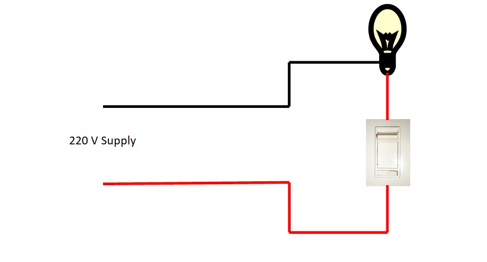
Wiring diagram for light switch
It is very easy to make a wiring diagram for a light switch. In this diagram, we have to use a single-pole switch which can turn our LED on and off. First, we need to connect our phase wire to one end of the switch terminal, then the other terminal of the switch to the light. The remaining neutral wire is connected to the other end of our led lights. So this is the simple wiring diagram of an LED switch. For more details, the circuit diagram is given below.
Wiring diagram for ceiling fan
It is also very easy to make a wiring diagram for ceiling. In this picture we have to use fan regulator which can turn on and off our fan as well as control the speed of fan. First, we need to connect our phase wire to one end of the regulator terminal, then connect the other terminal of the switch to the fan. The remaining neutral wire is connected to the other end of our fan. So this is a simple wiring diagram of a ceiling fan. For more details, the circuit diagram is given below.

Read Also