Table of Contents
What is Rupture Disc
After safety valves (PSV/PRV), rupture discs are the pressure relief (protection) device that is most frequently utilised in industrial applications. Rupture Disk is essentially a non-reclosing pressure relief safety device that guards against over pressurization or possibly harmful vacuum circumstances. The terms “rupture disc” and “burst diaphragm” are also frequently used to refer to the same thing. It comprises of a one-time-use membrane that ruptures at a predetermined pressure difference between the device’s inlet and outlet (i.e., defined breaking point), which can be positive or vacuum, to release the pressure and a disc holder.
Why rupture Discs are required
Designed to break at a specific pressure and temperature, a rupture disc is a sensitive relief device. It is a technique for offering personnel and equipment protection. It must therefore be a fail-safe device. When a pressure release device needs to open completely and instantly, rupture discs are used. The most popular pressure protection tool in industrial plants, after safety valves, is the rupture disc. They shield pipes and vessels from damage and deformation. The key goal is to keep the system up and running as long as possible while providing optimal protection.
Types of Rupture Disc
There are various varieties of rupture discs, depending on their usefulness and applications. Metals or plastics are used to make them most often (Inconel, Hastelloy, or Tantalum, plastic liners such as PTFE or FEP.). There are two types of dome rupture discs.
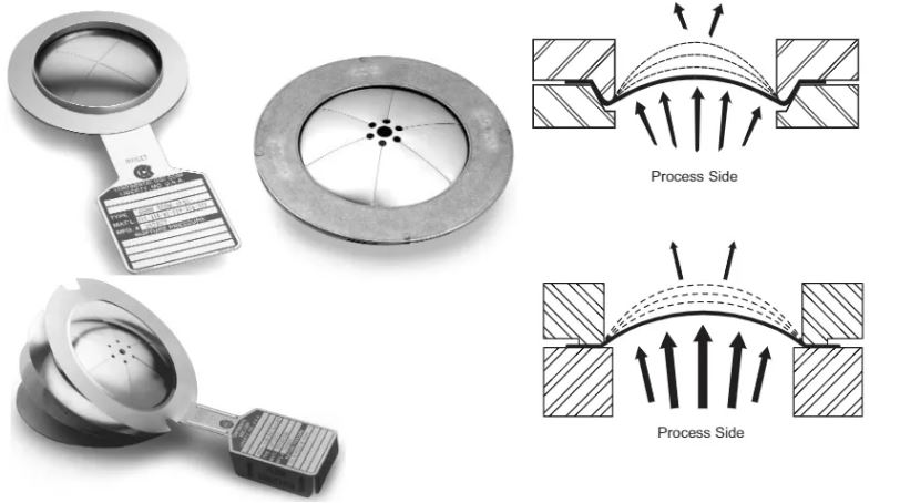
Reverse acting rupture disc
Reverse acting rupture discs with a dome facing the process’s direction allow for extremely high operating pressures and operating pressure ratios.

Forward acting rupture disc
In forward acting rupture discs have a dome that faces away from the process.
Compact rupture discs
These rupture discs, which frequently use adhesive bonding or soldering to attach to the housing or holder, are typically quite small in size, depending on whether they are forward-acting or reverse-acting.
Difference Between a Forward-Acting Rupture Disc and a Reverse-Acting Rupture Disc
The major differences between Reverse-Acting Rupture Disc and Forward-Acting Rupture Disc are mentioned below.
Forward Acting Rupture Disc
- The process media are on the concave side of the dome.
- operates when the disc’s weakest area exceeds its tensile strength. They are intended to operate under tension.
- reduced cycle life as a result of tensile stress generation that encourages fracture growth.
- To avoid the dome moving before reversal, Forward-Acting Rupture Discs are normally not supported on the outlet side.
- Comparably less expensive.
Reverse Acting Rupture Disc
- The dome’s convex side is facing the process medium.
- operates when the pressure causes the dome to become unstable, causing the dome to reverse or buckle. They are made to operate in compression.
- extended cycle life, and compressive stresses are created. therefore, less crack spread.
- To stop the dome from moving before reversal, domes are normally supported on the outlet side.
- Comparably Costly
Components of Rupture Disc | Parts of Rupture Disc
A rupture Disc has the below components or parts.
- Rupture Disc
- Rupture Disc Holder
- Heat Shield
- Baffle Plates
- Alarm system to transmit the rupture disc opening signal
Materials of Rupture Disc | Rupture Disc Material
Any material that the process fluid allows for construction of rupture discs is acceptable. The following materials are typically used to make industrial rupture discs.
- Carbon Steel
- Graphite
- Inconel
- Tantalum
- Monel
- Nickel
- Aluminum
- Stainless steel
- Hastelloy
Advantages of Rupture Disc
In comparison to electrical, pneumatic, or spring-loaded safety systems, rupture discs provide a number of advantages.
Performance of rupture discs that is foolproof.
Economical.
high dependability to avoid unneeded system downtime.
has no moving parts and a simple design.
Both overpressure protection and depressurization protection.
tightness leaks.
fewer fugitive emissions because there was no boiling or leaking before the explosion.
React swiftly enough to rapidly release the added strain.
Lightweight.
used in applications that handle liquid or gas.
There is no extra charge for maintenance for each ruptured disc per service.
greater temperature sensitivity
Protect against sudden pressure rises caused by internal fires, runaway reactions, or ruptured heat exchanger tubes.
Disadvantages of Rupture Disc
There are a few disadvantages to ruptured discs, though. Which are:
It is impossible to test before use.
Deteriorate with time or as a result of corrosion.
Every time it ruptures, it needs to be replaced. Thus, a shutdown may be necessary for the refit.
Installation must be done with caution so as not to harm the rupture disc.
During installation, improper bolt torque may also have an impact on the burst pressure of the disc.
Difference between a relief or safety valve and a rupture disc
A rupture disc is a type of emergency relief device that uses a thin metal diaphragm that is deliberately engineered to burst at a specific pressure. The fact that the valve reseats while the disc does not distinguishes a relief or safety valve from a rupture disc. Installation options for rupture discs and a relief valve include parallel and series. The space between the disc and the valve needs to be kept at atmospheric pressure to prevent an erroneous pressure differential from existing. A rupture disc is typically built to release at 1.5 times the vessel’s maximum permissible working pressure. Low rupture pressure, high temperatures, and corrosion are three significant factors that must be considered when estimating a disc’s size.
The kind of material utilised in a disc depends on how corrosive a system is. Corrosion of any size can significantly reduce disc life. The number of fittings and bends in the discharge pipe for rupture discs, safety valves, and relief valves should be kept to a minimum. The valve should only be under minimal load, and any piping utilised should have sufficient supports and expansion joints.
Purpose of Rupture Disc | Rupture Disc Applications
Rupture Discs are also used in situations where a relief device must have “zero” leakage. These gadgets can also be used as “rapid opening” valves when connected in series.
Rupture discs can be utilised for several purposes, such as “rapid opening” valves, main relief, secondary relief, in series with a relief valve, and other purposes.
Initial Relief
The rupture disc is the only tool used for pressure release when employed as main relief. It benefits from being leak-tight, having a quick response time, having a minimal pressure drop, being the least expensive, having a very high reliability, and requiring little maintenance. Its drawback is that it needs to be changed every time a rupture occurs. It permits venting up until the system pressure reaches the downstream pressure.
Additional Support
When utilised as a secondary relief mechanism, the rupture disc acts as a backup vent to a major relief device, typically a Relief valve. Its function in this situation is typically to offer supplemental security against a major disaster that is unlikely but yet possible and could exceed the capability of the primary relief device.
Coupled with a relief valve
The rupture disc is often mounted upstream of the valve when used in series with a pressure relief valve. The valve will be shielded by the disc from process material that might corrode or obstruct it. Unless the disc ruptures, it can also serve as a seal, blocking any leaking through the valve.
A pressure gauge, try cock, free vent, or other suitable telltale indicator must be installed in the gap between the rupture disc and the pressure Relief valve. The typical setup consists of a pressure gauge and an excess flow valve. This setup aims to either completely rule out the development of backpressure or make its identification easier. Because a disc reacts to the differential pressure acting on it, if a back pressure is allowed to exist in this cavity, the disc won’t rupture at the rated pressure. Relief valves that discharge into common manifolds can be protected from process or corrosive media by installing a low-pressure rupture disc on the downstream side of the valve. To avoid the build-up of pressure that could negatively impact the Relief valve set pressure, the area between the Relief valve outlet and the rupture disc needs to be vented. For this function, an excess flow valve will do.
Other Purposes
A rupture disk’s low inertia properties result in an opening time from a closed and sealed state to a fully open state that is less than 0.5 milliseconds (0.0005 sec.). A rupture disc can behave as a “rapid opening” valve. Examples of applications for rupture discs include: 1) shock tube operations, 2) seismic testing, 3) simulating the firing of large calibre guns, 4) moving control mechanisms from a distance, and 5) injection systems for the suppression of upsets in storage containers or systems.
How should a Rupture Disc be chosen?
There is no industry standard for rupture discs. Therefore, a number of factors must be taken into account to choose the best. A few of the factors to consider when choosing a rupture disc are as follows:
- Operational conditions for lines.
- Pipe size (The nominal pipe size DN or NPS specifies the rupture discs’ diameter to match the diameter of the pipes or flanges).
- The pressure at which the rupture disc opens is referred to as the burst or set pressure. The rupture disc is chosen so that it opens up before any system harm occurs. Normally, it is at the appropriate temperature and pressure (below the maximum permitted working pressure during regular operation).
- Vacuum pressure or permissible overpressure
- Process medium.
- Vacuum resistance.
- Pulsation.
- Vent area requirements or flow rate specifications.
Burst tolerance
Specified range within which the rupture disc can open at a given burst or fixed pressure. A ruptured disc, for instance, will open between 9 bar and 11 bar if the defined burst pressure is 10 bar and the burst tolerance is +/-10%.
Application phase
Gas only rupture discs should only be utilised with gaseous media.
Rupture Disc Operating Ratio
This is the operating pressure at which a rupture disc can be used for a long time. Ruptured discs can operate at a maximum operating ratio of between 50 and 95%, depending on the design and materials employed. In order for a rupture disc to function properly, this ratio must be taken into account.
Design of Rupture Disc
Rupture discs can be either flat or domed, round or square, and have one or more layers. Many rupture discs have breaking points that can be made, for instance, using lasers. These could be straightforward cuts or even unique geometry. The rupture element refers to this area of the rupture discs. Different rupture disc kinds are needed for various purposes. They can be flat or domed and are made of one or more layers of metal or plastic. Domed rupture discs might have the dome facing the process or away from it. There are numerous conceivable combinations within each of these kinds.
Installation of Rupture Disc | How to Install Rupture Disc
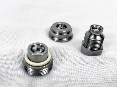
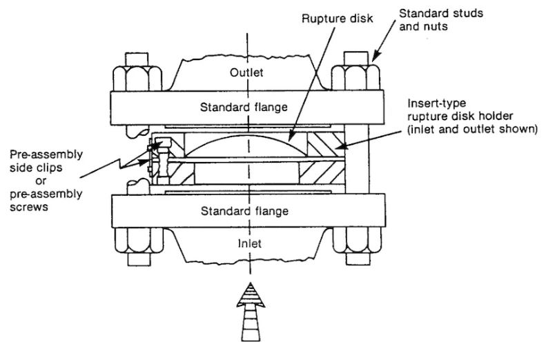
Either rupture discs are mounted directly between flanges, or they are inserted into the appropriate ruptured disc holder and mounted between flanges. In some instances, the manufacturer already soldered or welded the rupture disc into the holder. The required connections, such as thread (NPT, G or customer-specific thread), connection systems (such as VCR), or various flanges (ISO-K, KF, ISO-F, CF), are then installed on these holders.
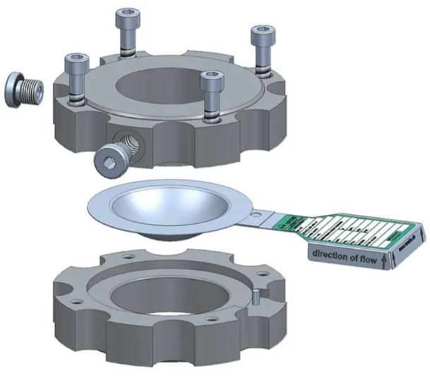
To obtain alarm as soon as a ruptured disc is triggered (opened), a wide variety of signalling mechanisms are available. A tripping wire mounted to the rupture disc and connected to the process control system is the simplest way to accomplish this. The wire breaks, the circuit is broken, and the process control system is informed that the rupture disc has been triggered by the opening of the bursting disc. Non-invasive signalling techniques (such magnetic proximity sensor) are utilised when there are very high demands for leak-tightness.
Ruptured disc manufacturers
Some of ruptured disc manufacturers are as below.
- Fike.
- BS&B Safety Systems.
- Continental Disc.
- Aquatech.
- Halma.
- Pentair.
- Flammer.
- A.M. Enterprises.
- RIECO Industries Limited.
Read Also
- Temperature Measurement
- Thermometer | Types of Thermometer
- Celsius to fahrenheit | fahrenheit to celsius Converter online
- Control System Control valve Classification
- Actuator Classification
- Various type of valve accessories used in control valve
- Hazardous Area Classification