Table of Contents
Priority encoder is used to solve the issues in binary encoder which generate wrong output when more than one input line is active high. Priority encoder works on highest priority input. The highest priority is consider first to generate the output. A priority encoder is a type of encoder circuit that includes the priority function. The procedure of the priority encoder is such that if two or more inputs are equal to 1 at the same period, the input having the highest priority will take precedence. Similar to a digital encoder, It also converts 2N input line into N output line.
The Priority Encoder is another type of combinational circuit similar to a binary encoder, except that it generates an output code based on the highest prioritized input. Priority encoders are used extensively in digital and computer systems as microprocessor interrupt controllers where they detect the highest priority input.
Priority Encoder truth table-
The truth table of priority(four input) encoder is given in Table. In addition to the two outputs x and y , the circuit has a third output indicate by V ; this is a valid bit indicator that is set to 1 when one or more inputs are equal to 1. If all inputs are 0, then no valid input and V is equal to 0. The other two outputs are not inspected when V equals 0 and are specified as don’t-care conditions. If all inputs are 0, V is cleared to 0 and the other outputs of the encoder are not used, so they are signified with don’t care condition. This is because the vector address is not shared with the CPU when V = 0. The Boolean function showed in the table determines the internal logic of the encoder. Generally, a computer will have more than four interrupt sources. A priority encoder with eight inputs, for example, will create an output of three bits.
| INPUT | OUTPUT | |||||
| D3 | D2 | D1 | D0 | x | y | V |
| 0 | 0 | 0 | 0 | X | X | 0 |
| 0 | 0 | 0 | 1 | 0 | 0 | 1 |
| 0 | 0 | 1 | X | 0 | 1 | 1 |
| 0 | 1 | X | X | 1 | 0 | 1 |
| 1 | X | X | X | 1 | 1 | 1 |
Note that whereas X is output columns which is represent don’t-care conditions.
x is in the input columns are useful for representing a truth table in condensed form.
The truth table uses an X to represent either 1 or 0. For example, X 100 represents the two minterms 0100 and 1100. According to Table , the higher the subscript number, the higher the priority of the input. Input D3 has the highest priority, so, regardless of the values of the other inputs, when this input is 1, the output for xy is 11 (binary 3). D2 has the next priority level. The output is 10 if D2 = 1, provided that D3 = 0, regardless of the values of the other two lower priority inputs. The output for D1 is generated only if higher priority inputs are 0, and so on down the priority levels.
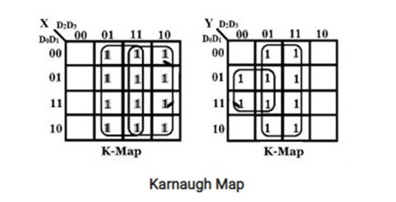
x = D2 + D3
y = D3 + D1 D2‘
V = D0 + D1 + D2 + D3
Combinational logic of priority encoder:-
In priority encoder, there are 03 OR Gate and 01 AND Gate and other 01 NOT Gate to make logical diagram of priority encoder. there are four input(D3,D2,D1,D0) and two output(x, y) and enable output represent V. Whenever any input high then V is enable to communicate to processor. The priority encoders output corresponds to the currently active input which has the highest priority. So when an input with a higher priority is present, all other inputs with a lower priority will be ignored.

The output of the priority encoder can form part of the vector address for each interrupt source. The other bits of the vector address can be created any value. For instance, the vector address can be formed by joining six zeroes to the x and y outputs of the encoder. With this choice, the interrupt vector for the four I/O devices is created binary numbers 0, 1, 2, and 3.
Application of priority encoder:-
A larger priority encoder can be designed through cascading different priority encoders. Thus, this kind of encoder is used to decrease the number of required connections within a specific application where there are several inputs. In electrical and electronic circuits, priority encoder is used to reduce the requirement of connecting wires which includes several inputs. This is also controls the interrupt requests by performing on the maximum priority demand to encode the flash analog output to the digital converter. magnetic positional control which is utilized in the positioning of the robotic arm as well as navigations of the ship. In this situation, the encoder changes to a digital code from the angular location of a compass. So priority encoder remove this drawback of the encoder and it provides a coded output through allocating a priority toward the input bits. It is frequently used once several components share a common resource otherwise within interrupt controllers and Using a PPC (parallel prefix computation), improves calculation as well as circuit timing.
therefore, this is all about an overview of the priority encoder. This is a special type of encoder, used to compensate the problem associated with normal encoders. In this encoder, priority increases when the movement is in a downward direction.
To read more about following topics, click on individual links below-
- What is an Encoder?
- Encoding types
- Encoder and Decoder
- Optical Encoder
- Encoding meaning in hindi
- Different Types of display devices
- Digital Electronics