Table of Contents
What is Optical encoder-
Optical encoder is a transducer commonly used to measure rotational speed. It consists of a shaft connected to a circular disc, with one or more tracks of alternating transparent and opaque spheres. A light source and an optical sensor are mounted on opposite sides of track. When the shaft rotates, the light sensor emits a series of pulses as the light source is interrupted by patterns on the disc. This output signal can be directly proportional with digital circuitry. The number of output pulses per rotation of the disc is a known number, so the number of output pulses per second can be directly converted into the shaft’s rotational speed (or rotations per second) and commonly used in motor speed control applications.

Construction-
The optical encoder is composed of a light-emitting device (LED), photo sensors, and a disc called a code wheel with holes in the radial direction and detects rotational position information as an optical pulse signal. When a code wheel attached to a rotating shaft such as a motor rotates, an optical pulse is generated based on whether light emitted from a fixed light-emitting element passes through a hole of the code wheel or not. The photo sensor detects the optical pulse, converts it into an electrical signal, and outputs it Light-emitting devices used in optical encoders are generally inexpensive infrared LEDs, but color LEDs with shorter wavelengths are sometimes used to suppress light diffusion and laser diodes are used in applications that require high performance. The code wheel is a disc with holes for passing/blocking the light emitted from the LED.
The material of the code wheel is metal, glass and resin. Metal is strong robustness against temperature and vibration, humidity and is used in the industrial field. Resin is cheap and suitable for mass production and also used for consumer applications. The material of code wheel Glass is used in applications where high resolution and precision are required. In addition, a fixed hole can be placed at the position facing the code wheel in order to clarify the passing / blocking of the light that passes through the code wheel and enters the light receiving element.
Incremental optical encoder-
An incremental optical encoder consists of two tracks, 90 degrees out of phase with each other, producing two outputs. The relative phase between the two channels shows whether the encoder rotating clockwise or counter clockwise. There is often a third track that generates a single index pulse to indicate an absolute position reference. Otherwise, an incremental encoder gives only relative position information. The interface circuitry or computer should keep track of the absolute position.
Digital tachometer-
A digital tachometer, often known as an optical encoder or simply an encoder, is a mechanical-to-electrical conversion device. The shaft of the encoder is rotated and gives an output signal, which is proportional to the distance (i.e. angle) to which the shaft is rotated. The output signal may be square or sinusoidal waves, or may provide an absolute position. Therefore, encoders are classified into two basic types’ absolute encoders and incremental encoders. The absolute encoder assigns a unique address for each shaft position through 360°. This type of encoder employs contact (brush) or non-contact methods of sensing position. However, the incremental encoder provides either pulses or a sinusoidal output signal as it is rotated by 360°. Thus, distance figures are obtained by counting this information.
Absolute optical encoder-
An absolute optical encoder consists of multiple tracks, each with a different pattern, to produce a binary code output that is unique to each encoded position. There is one track for each output bit, so an 8-bit complete encoder has 8 tracks, 8 outputs, and 256 output combinations, for a resolution of 360/256 = 1.4°. Encoding is not always a simple binary counting pattern, as it results in adjacency counts where many bits change at once, increasing the potential for noise and read errors. A Gray code is often used, as it produces a pattern where each adjacent count results in only a single bit change. A full encoder is usually much more expensive than a comparable incremental encoder. Its main advantage is the ability to retain absolute status information even when power to the system is removed.
Principle of optical encoder :-
Optical encoders are analyzed into two types, according to their structure. They are the “transmissive type” in which the light emitting device (LED) and photo sensor sandwich the code wheel, and the “reflective type” in which the LED and photo sensor are placed on the same side and the code wheel reflects the light. Transmission type, the photo sensor is a device used to determine presence or absence of an object which object detects whether the light emitted from the LED passes through the hole in the code wheel or not . The advantage is signal accuracy easy to improve and due to relatively simple optical path can be easy developed. Reflective type, when the light emitted from the LED is reflected by the code wheel then the photo sensor detects.
The resolution of an optical encoder is basically determined by the number of slits in the code wheel. Therefore, it is necessary to increase the number of slits in the code wheel to achieve higher resolution, but to reduce the area of each slit to be compatible with encoder miniaturization.
As a result, high precision is required to assemble the components, and physical limits are reached somewhere.
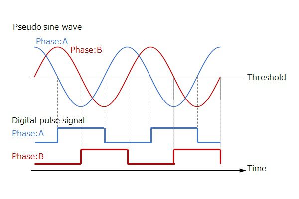
To further improve the resolution, there is a method of “electrical interpolation” of the A phase and B phase of the output signal using a pseudo sine wave signal instead of a pulse signal.
In this way, the optical encoder can realize high resolution and high accuracy by optimizing the structure of LED, code wheel, photo sensor, etc., and reducing the distortion of pseudo sine wave.
Advantage of optical encoder-
- Easy to improve accuracy and resolution than magnetic encoder and easily to be used
- Low cost feedback
- Immune to interface
- Flexible mounting option
Application of optical encoder-
it is used for servo control and hollow through shaft type motor control that require high precision as well as it is not affected by the surrounding magnetic field, their applications where a strong magnetic field is generated it can be used. So, it is used in devices that use large-diameter motors and use in relatively low reliability and low resolution applications.
To read more about following topics, click on individual links below-
- What is an Encoder?
- Encoding types
- Priority encoder
- Encoder and decoder
- Encoding meaning in hindi
- Different Types of display devices
- Digital Electronics