Table of Contents
This Article establishes the minimum guidelines for E&I Technicians and/or contractors to perform the maintenance on Control Valve (assembling & de- assembling). This document also enables E&I technicians to do primary level configuration and troubleshooting.
Scope and responsibility
- This document is applicable for Calibration of Samson control valves .
- E&I Technicians are responsible to follow the steps as mentioned in this procedure.
- E&I Manager and Instrumentation Engineers are responsible for the implementation of this procedure.
Competency Requirements
E&I Technicians must be trained and qualified to perform calibration of control Valve.
Definition
The Control Valve is a final control element which works to restrict the flow of fluid through a pipe at the command of an automated signal, such as the signal from a loop controller or logic device (such as a PLC). Some control valve designs are intended for discrete (on/off) control of fluid flow, while others are designed to throttle fluid flow somewhere between fully open and fully closed (shut), inclusive.
These are used in a process industry for the controlling of process parameters e.g. – flow, level, pressure etc.
References
Procedure requirement
There are some procedure given below-
Safety Precautions
- Ensure that tools necessary for performing the task i.e. Screw Driver set, Allen key, D-Spanner etc.
- If the Control valve is an EIS, take necessary precautions for maintenance of EIS & follow EIS procedure too.
- The plug stem extension may not be twisted at all; otherwise the metal bellows could be damaged.
- Wrong implementation of procedure/implementation without proper communication may lead to accidents or plant disturbance.
Maintenance Procedure
Proper procedure is necessary to ensure the satisfactory operation.
- Ensure the Work order (print copy after WO released) is ready to perform the calibration on Control valve.
- Ensure the work permit/Maintenance request form to confirm the maintenance on control valve.
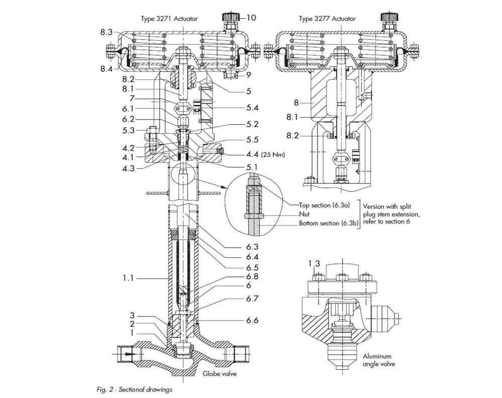
- An Schematic Diagram of Control Valve is mentioned as follows with various parts name.
Legend to Fig.
1. Valve body
1.1 Cryogenic extension bonnet
1.3 Nuts
2. Seat
3. Plug
4.1 Spring
4.2 Packing 4.3 Washer 4.4 Test connection
5. Valve bonnet 5.1 Guide bushing 5.2 Threaded bushing 5.3 Nuts 5.4 Travel scale indicator 5.5 Seal
6. Plug stem 6.1 Stem connector nut 6.2 Lock nut 6.6 Guide bushing (not with 4” and 6”/Class 150 – 300, version with split plug stem extension)
6.3 Plug stem extension with metal bellows 6.3a and 6.3b with split extension bonnet 6.4 Bellows nut 6.5 Bellows flange 6.7 Nut(s) 6.8 Washers
7. Stem connector
8. Actuator 8.1 Actuator stem 8.2 Annular nut 8.3 Springs 8.4 Rolling diaphragm
9. Loading pressure connection
10. Venting plug
Assembling and Disassembling the Valve (split plug stem extension)
If the maintenance (having Seat replacement task) is carried out on the Cold Box installed control valve then a special tool (order no. 1280-3031, Fig. 4) is required for assembly and reassembly. Only the use of this tool guarantees that the metal bellows will not be damaged.
A procedure for disassembling & assembling the control valve is mentioned as follows-

Important-
- For actuators with fail-safe action “Actuator stem extends” and especially actuators with pre-tensioned springs apply a pressure beforehand to retract the actuator stem slightly.
- For actuators with fail-safe action “Actuator stem extends” and especially actuators with pre-tensioned springs, apply a pressure slightly higher than the lower signal pressure range (see actuator nameplate) to the loading pressure connection on the bottom diaphragm chamber, before loosening the annular nut (8.2).
Removing a mounted actuator-
- Disconnect instrument air supply & Valve positioner Loop signal (4-20)mA supply.
- Remove valve positioned by removing the linkage between valve positioned & control valve stem.
- Remove clamps of the stem connector (7) between actuator stem and plug stem and unscrew annular nut (8.2).
- Lift the actuator off the valve.
Disassembling valve-
- Place a wrench at the stem connector nut (6.1) to hold it stationary and loosen the lock nut (6.2). Unscrew stem connector nut and lock nut from the plug stem extension (6.3a).
- Unthread guide bushing (5.2) to relieve the tension from the packing (4.2).
- Unthread nuts (5.3) at the valve bonnet. Lift valve bonnet (5) carefully upwards off the flange of the cryogenic extension bonnet (1.1).
- Place the special tool with 24 mm socket wrench over the plug stem extension (6.3b) onto the nut (20) in such a way that the labeling “disassembles” faces upwards. (As the needle bearing of the tool can only be turned in one direction, it must be placed turned by 180° as required for assembly or disassembly.) Insert 17 mm socket wrench and unscrew the top section of the plug stem extension (6.3a) with socket wrench.
- In case of DN 100 and 150 (4″ and 6″), unscrew nut (20). In case of DN 25 to 80 (1″ to 3″) the nut remains on the plug stem extension.
- Insert seal (24) and fit on protective cap (23).
- Apply lubricant (order no. 8150-0116) or oxygen compatible / O2 service lubricants (e.g. Blue-gold) for cleaning purpose & to the protruding thread of the plug stem extension to prevent dirt and moisture from entering the plug stem extension.
- Screw on nut (22) and hand tighten to extract the plug stem extension to the dimension h (Table2). Do not tighten more than 10 Nm; otherwise the metal bellows will be damaged.
- Tighten nut (5.3) (tightening torque in Table 2).
- Insert stopper (25).
Assembling Valve
- Clean the control valve parts with O2 compatible cleaning agent to ensure the proper cleaning for O2 service before re-assemble.
- Remove stopper (25) and clean inside the protective cap.
- Unthread nut (22) with 24 mm socket wrench.
- Loosen nut (5.3) and remove protective cap (23).
- Place the special tool with 24 mm socket wrench in such a way that the labeling “assemble” faces upwards. In case of DN 100 and 150 (4″ and 6″) valves, screw on nut (20) as far as it will go by hand.
- Screw top section of the plug stem extension (6.3a) onto thread of the lower section (6.3b) by hand.
- Insert 17 mm socket wrench and tighten top section of the plug stem extension (6.3a) with the socket wrench, observing the tightening torques in Table 2.
- Insert seal (5.5) into flanged section. Slide valve bonnet carefully over the plug stem extension (6.3a) to ensure that the packing does not get damaged and place it on the flanged section.
- Screw on nut (5.3) and tighten.
- Tighten guide bushing (5.2) as far as it will go.
- Thread lock nut (6.2) and nut (6.1) loosely onto the plug stem extension (6.3a).
Mounting the actuator
- Loosen the lock nut (6.2) and stem connector nut (6.1) on the valve. Firmly press the plug with the plug stem into the seat. Then thread down the lock nut and stem connector nut.
- Remove clamps of the stem connector (7) and annular nut (8.2) on the actuator (8).
- Slide the annular nut over the plug stem extension.
- Place the actuator on the valve bonnet (5) and screw tight using the annular nut (8.2).
- Read the nameplate on the actuator to determine which bench range (signal range with pre-tensioned springs) and which operating mode of the actuator are used. The operating mode (fail-safe action) “Actuator stem extends” or “Actuator stem retracts” is indicated on the nameplate by FA or FE on the Type 3271 Actuator and by the appropriate symbol on the Type 3277 Actuator. The lower bench range corresponds to the lower signal pressure range to be adjusted; the upper bench range corresponds to the upper signal pressure range.
- For actuators with fail-safe action “Actuator stem extends”, apply the pressure corresponding to the lower signal pressure range (e.g. 0.2 bar) to the loading pressure connection on the bottom diaphragm chamber. For actuators with fail-safe action “Actuator stem retracts”, apply the pressure corresponding to the upper signal pressure range (e.g. 1 bar) to the loading pressure connection on the top diaphragm chamber.
- Manually turn the stem connector nut (6.1) until it touches the actuator stem (8.1) and then turn it a further 1/4 turn. Screw tight the lock nut (6.2) while holding the stem connector nut stationary to ensure that the plug stem extension (6.3) with the metal bellows is not twisted.
- Position clamps of the stem connector (7) and fasten
- Align travel indicator scale (5.4) with tip of the stem connector; for actuators with “Actuator stem extends” align it with lower marking (valve closed) and for actuators with “Actuator stem retracts” align it with top marking (valve open).
- Mount the Valve positioner & connect the instrument air supply.
Record Retention
- A Checklist must be filled after assembling the control valve for calibration of Valve positioned.
- Check list for calibration of Control Valve valve and calibration record must be filled before & after the calibration.
- All calibration records should be kept for at least three years & after that it should be disposed off.
Read Also
- Control Valve
- Actuator
- Control Valve Accessories
-
Control System | Type of Control Loop | Open loop | Close Loop