Table of Contents
Source and sink refer to the direction of current flow between an I/O point on an I/O module and the connected device. It is only relevant for DC circuits with positive and negative polarities because current flows both directions in an AC circuit. It is important to select a sink or source I/O module based on the devices that you are going to connect. If the incorrect type module is selected, your circuit will not function properly. What is source and sink in plants?
What is the difference between sink and source inputs?
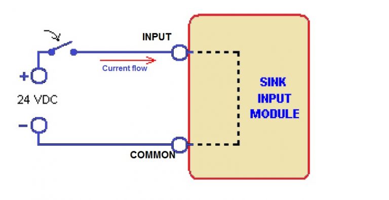
Sink input: –
In a sink input module, the current flow is from the connected device to the input. What is source and sink in plants?
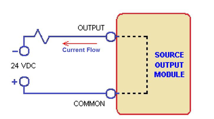
Source Input:-
In a source input module, the current flow is from the input to the connected device. What is source and sink in plants?
What is the difference between sink and source outputs?
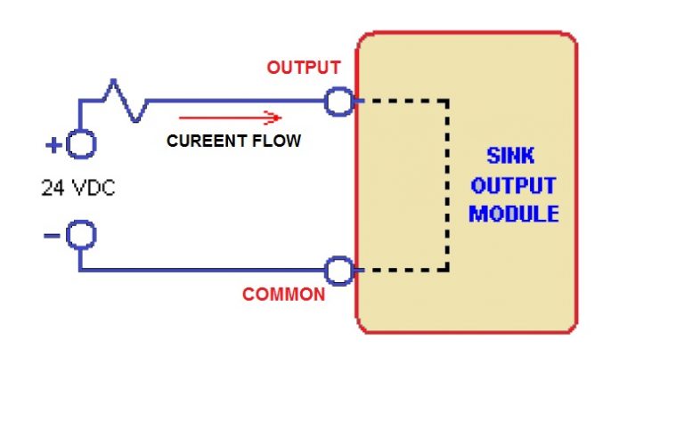
Sink Output:-
In a sink output module, the current flow is from the connected device to the output.
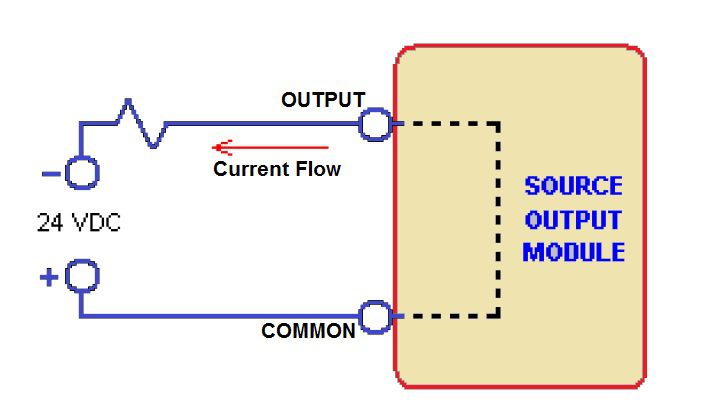
Source Output:-
In a source output module, the current flow is from the output to the connected device.
Let’s understand the source and sink in detail with an example.
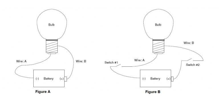
The circuit in Figure-A shows a light bulb that is connected to a battery with two wires. DC (direct current) flows from the battery, through the light bulb, and back to the battery. That is all it takes to light the bulb. Connect positive (+) to one side of the bulb, connect negative (-) to the other side of the bulb, and it turns on. This circuit contains the basic requirements of a digital system: a power source (the battery), a device that is turned on and off (the bulb) and wires to connect them together. Now we will add one more feature: suppose you want to turn the light on and off? You need to add a switch (or two?). Here is the big question: Do you add the switch to wire A or do you add switch to wire B? Or do you add two switches?
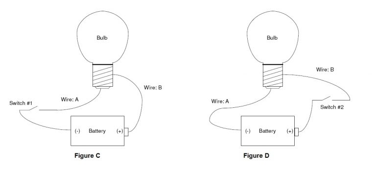
Figure-B shows two switches installed in the circuit. You already know that one switch will do the job. After all, you have been turning lights on and off just once switch. So what is the use of two switches where one will do the job? But which switch do you choose? Do you install a switch on Wire A as shown in Figure-C; or do you install a switch on Wire B as shown in Figure-D.
The answer is, it doesn’t make any difference; either switch will work fine! Either switch will break the flow of current through the circuit. Now here is the part that causes all of the confusion: we need a way to describe using switch 1 vs. switch 2.
If you examine Figure-C you will see that switch 1 is installed on the wire that runs from the negative (-) side of the battery to the light bulb. It means wiring connected in Sink mode.
You can see in Figure-D that switch 2 is installed on the wire that runs from the positive (+) side of the battery to the light bulb. It means wiring connected in source mode.
Read Next:-
2-wire,3wire and 4-wire Transmitter Wiring