Table of Contents
Following are the reasons Why 4 to 20 mA used?:-
- Current signals are often used in sensors because the current response is usually more linear than the voltage response.
- Current signals also typically provide a low impedance for sensors, with the benefit of better immunity to noise.
- Current signals can extend much further than voltage signals, allowing robust signal wire lengths of up to 1,000 meters.
- 4-20mA current loops is safe enough. Even if the power supply is 24 volts, shock isn’t a danger .
- 4-20mA current loop is intrinsically safe for hazardous areas.
Let us understand the 4 to 20 mA signal by the step by step-Why 4 to 20 mA used?
Current Loop Basics
Current loop is a very robust sensor signaling standard. Current loops are ideal for data transmission. All the signaling current flows through all components; the same current flows even if the wire terminations are less than perfect. All the components in the loop drop voltage due to the signaling current flowing through them. The signaling current is not affected as long as the power supply voltage is greater than the sum of the voltage drops around the loop at the maximum signaling current.
Figure shows a schematic of the simplest 4 to 20mA current loop. There are four components,
1. A DC power supply;
2. A 2-wire transmitter;
3. A receiver resistor that converts the current signal to a voltage; and
4. The wire that interconnects it all. Two Rwires exist since you have a wire out to the sensors and another back. Why 4 to 20 mA used?
Current supplied from the power supply flows through the wire to the transmitter. The transmitter regulates the current flow. The transmitter only allows a current proportional to the measured parameter to flow, called the loop current. The current flows back to the controller through the wire.
The loop current flows through Receiver to ground and returns to the power supply. The current flowing through Receiver produces a voltage that is easily measured by an analog input. For a 250Ω resistor, the voltage will be 1 VDC at 4 mA and 5VDC at 20mA.
What is a 4-20 mA current loop?
The 4-20 mA current loop has been the standard for signal transmission and electronic control in control systems since the 1950’s. In a current loop, the current signal is drawn from a dc power supply, flows through the transmitter, into the controller and then back to the power supply in a series circuit. The advantage is that the current value does not degrade over long distances, so the current signal remains constant through all components in the loop. As a result, the accuracy of the signal is not affected by a voltage drop in the interconnecting wiring. Why 4 to 20 mA used?
4 to 20 mA current signals
The most popular form of signal transmission used in modern industrial instrumentation systems (as of this writing) is the 4 to 20 milliamp DC standard. This is an analog signal standard, meaning that the electric current is used to proportionately represent measurements or command signals. Typically, a 4 milliamp current value represents 0% of scale, a 20 milliamp current value represents 100% of scale, and any current value in between 4 and 20 milliamps represents a commensurate Percentage in between 0% and 100%.
In process instrumentation, sensors are used to measure physical quantities such as pressure, temperature, flow etc. of the process. The sensor generates output in the form of voltage which is sent to the transmitter attached with the sensor. The transmitter converts voltage signal into current signal. The range of current signal that the transmitter generates at the output is decided through the calibration of the transmitter. Almost all transmitters that are manufactured on industrial process standards can produce current signal in the range of 4-20mA. This is an analog signal standard, meaning that the electric current is used to proportionately represent measurements or command signals. Typically, a 4 milliamp current value represents 0% of scale, a 20 milliamp current value represents 100% of scale, and any current value in between 4 and 20 milliamps represents a commensurate percentage in between 0% and 100%.
For example, if we were to calibrate a 4-20 mA Pressure transmitter for a measurement range Of 0 to 10 Kg/cm2, we could relate the current and measured pressure values by a table that is given below:-
|
Current (mA) |
Measured Value(Kg/cm2) |
|
4 |
0 |
|
8 |
2.5 |
|
12 |
5 |
|
16 |
7.5 |
|
20 |
10 |
What is the use of 4 to 20 mA signal in control system?
DC current signals are also used in control systems to command the positioning of a final control Element, such as a control valve. Normally (Not In all case) 4 mA signal close the valve and 20mA signal open the valve.
Most industrial control systems use at least two different 4-20 mA signals.
- For process variable (PV)
- For manipulated variable(MV)

The relationship between the two singles depends on the response of the controller. It is not necessary that both signals are equal if the controller is reverse acting, both signals will be reverse. This will depend on the response from the controller and the demand for the process.
Why 4 to 20 mA used instead of 0-20 mA?
Reason 1:- The primary reason that 4-20mA is used instead of 0-20mA is because an elevated ‘zero’ allows for powering the field device on the same two wires that the signal uses. Passive, loop powered field transmitters use the DC electrical current below 3.5mA to power the transmitter to make the measurement. The voltage is provided by the loop power supply and the loop current is regulated by the field transmitter which acts as a transmitter, regulating the loop current in proportion to the measurement. The aspect of power-over the-wires is what drives the market for passive, 2 wire, loop-powered field instruments because otherwise they would have to be 3 or 4 wire units, with the increased installation cost. Most all field transmitters will drive slightly below 4.00mA and above 20.00mA for signal outside the calibrated range. And there’s a fail-low setting at about 3.6mA (varies depending on vendor) to signal the loss of a true measurement. But the current below 3.5mA is ‘reserved’ for powering the transmitter.
Reason 2 :- The elevated (live zero) is convenient for detecting broken wire open circuits. Suppose a transmitter whose range is 0 to 20 kg/cm2 to measure the pressure of a pipeline. When there is no pressure in the line, the transmitter will show 0 and the transmitter will out 4 mA. And when the full pressure on the line is 20 kg/cm2, the transmitter will out 20 mA. On the other hand if the output of the transmitter is 0 to 20 mA, then the transmitter will out 0 mA when pressure is reached and the transmitter will out 0 mA even when the wire breaks. In this case, it would be extremely difficult to identify that either 0mA current is due to open circuit of the transmitter or it is due to no pressure of the fluid. Hence, if the transmitter is calibrated to generate current signal in the range of 4-20mA, the faults like open circuits can easily be detected. Why 4 to 20 mA used?
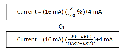
Calculation For 4 To 20 mA Signals
Given the linear relationship between signal percentage and milliamps, the equation takes the form of the standard slope-intercept line equation y = mx + c. Here, y is the equivalent current in milliamps, x is the desired percentage of signal, m is the span of the 4-20 mA range (16 mA), and c is the offset value, or the “live zero” of 4 mA.
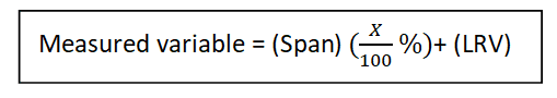
This equation form is identical to the one used to calculate pneumatic instrument signal pressures(The 3 to 15 PSI standard):

The same mathematical relationship holds for any linear measurement range. Given a percentage Of range x, the measured variable is equal to:
Some practical examples of calculations between milliamp current values and process variable values follow:
Example 1 :- A pressure transmitter range is 0 to 20 Kg/cm2 . Find the mA at 12 Kg/cm2 ?
Given :- Range – 0 to 20 Kg/cm2
LRV = 0
URV = 20
Span = URV-LRV
= 20-0
= 20 Kg/cm2
Apply formula no . 1
mA(current) = (16 mA){(PV-LRV)/(URV-LRV)} +4 mA
= 16* (12-0)/(20-0)+4
= 16*(12/20)+4
= 13.6 mA
mA(current) = 13.6 mA
Example 2:- A pressure transmitter has a calibrated measurement range of 50 to 100 kg/cm2 and an output range of 4 to 20mA. What is the expected output if the input is 75 kg/cm2?
Given :- Range = 50 to 100 kg/cm2
LRV = 50 KG/CM2
URV = 100 KG/CM2
SPAN = URV – LRV
= 100 – 50
= 50
Apply formula no . 1
mA(current) = (16 mA){(PV-LRV)/(URV-LRV)} +4 mA
= 16* (75-50)/(100-50)+4
= 16*(25/50)+4
= 12 mA
mA(current) = 12 mA
Example 3:- A temperature transmitter calibrated range is -200 to 300 degC and an output range of 4 to 20 mA. What is the PV at 12mA?
Given :- Range = -200 to 300 kg/cm2
LRV = -200 KG/CM2
URV = 300 KG/CM2
SPAN = URV – LRV
= 300 –(-200)
= 500
mA = 12 mA
PV = ?
Formula
mA(current) = (16 mA) +4 mA
PV = {(mA-4)/16*(URV-LRV)}+LRV
= {(12-4)/16*(300-(-200))}+(-200)
= 8/16*500-200
= 250-200
= 50
PV = 50 DegC
Read Also:-
2-wire, 3-wire, 4-wire Transmitter wiring
What is the concept of source and sink ?
Related Search:-

Fundamentals of 4-20 mA Current Loops
Fundamentals of 4-20 mA Current Loops

4-20 mA Transmitter Wiring Types: 2-Wire, 3-Wire, 4-Wire
4-20 mA Transmitter Wiring Types: 2-Wire, 3-Wire, 4-Wire
Smart Positioners

Pressure Gauge Calibration
Pressure Gauge Calibration

Proximity Switch
Proximity Switch
