Table of Contents
Rectifier
A rectifier is a device which convert AC( alternating current) to DC(direct current). It is a non linear, unidirectional device. An electrical current can only flow in one direction through a rectifier, which is likened to a one-way valve. Rectification is the process of converting AC current to DC current. A rectifier can physically exist in a variety of shapes, including solid-state diodes, vacuum tube diodes, mercury-arc valves, silicon-controlled rectifiers, and numerous other silicon-based semiconductor switches.

A rectifier is an electrical device that transforms alternating current into direct current using one or more P-N junction diodes. Rectification is the term used to describe this process because it is known to “straighten” the current’s direction also. In the forward bias condition, PN junction diodes only permit current; in the reverse bias condition, they block it. Almost all rectifiers have one or more diodes in certain configurations. A rectifier can produce a variety of waveforms, including:
Half Wave: The other wave is blocked while the positive or negative wave is passed through. Due to the fact that only half of the input wave shape is output, it is inefficient.
Full Wave: Reverses the negative portion of the AC waveform and merges it with the positive to create a whole wave.
Single-Phase AC: If the transformer is center-tapped, two diodes can combine to create a full-wave rectifier. If there isn’t a center-tap, four diodes need to be set up in a bridge.
AC in three phases: typically employs three pairs of diodes.
Because AC power fluctuates between peaks and valleys, rectifiers frequently fail to provide a steady DC voltage. For the power rectifier to produce a smooth DC current, a smoothing circuit or filter is typically required.
What is the rectifier’s principle?
A rectifier is a device that transforms alternating current into a single-direction or pulsing form of direct current. It is known as rectification when alternating currents are transformed into a form of direct current.


Types of Rectifier:
There are mainly two types of rectifiers.
1.Uncontrolled Rectifier
2.Controlled Rectifier
This rectifier’s input is rectified using diodes. As a unidirectional device, this diode only permits one direction of electrical flow.
The diode configuration of the rectifier prevents power from fluctuating depending on the load requirement. The following categories further divide uncontrolled rectifiers:
1.Half wave Rectifier
2.Full wave Rectifier
Half wave Rectifier-
Only the first half of an alternating current cycle is converted into direct current using a half-wave rectifier.
Working of Half wave rectifier:
An AC voltage waveform’s first half-cycle can pass through a half-wave rectifier, but the second half-cycle cannot.
The half-wave rectifier’s operating principle is:


Throughout the first half of the AC input cycle, leave the secondary S of the transformer’s end A at a positive potential and the end B at a negative potential.
In this instance, the diode is forward-biased, and current flows across the circuit. As a result, a voltage across load RL is acquired as the output.
During the second half of the AC input, the secondary S of the transformer’s end A is at a negative potential, and diode D is biassed in the opposite direction. We consequently get the output voltage shown in the diagram. Even if the output voltage still changes in magnitude, it is regarded as rectified when it is restricted to only one direction.
Because only half of the AC wave input may be rectified by the circuit, the device is referred to as a half-wave rectifier.
Building a Half wave Rectifier:
The components of a half-wave rectifier are as follows:
Here is an illustration of a half-wave rectifier. The AC input voltage is fed into the primary coil P of a suitable step-down transformer.
The load resistance RL and the semiconductor p-n junction diode D are connected to the secondary coil S of the transformer.
Full wave Rectifier-
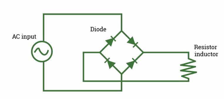
On the other hand, a full-wave rectifier transforms both the positive and negative half cycles of the AC. An illustration of this is the bridge rectifier. It is constructed from four diodes joined together in a Wheatstone bridge.
Working of full wave rectifier:
A full-wave rectifier produces pulsating direct current by converting an entire cycle of alternating electricity. The full-wave rectifier’s operating principle is:
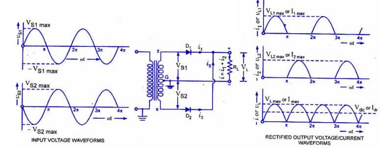
When an AC supply is applied to the i/p during both half cycles of this sort of rectifier, the current flowing through the load moves in the same direction. Because both polarities of the i/p waveform are changed to pulsing DC in this circuit, a larger standard output voltage is produced. This type of rectification can be accomplished by utilising no more than two crystal diodes with differing current conductivities.


The following two circuits, a centre tap full wave rectifier and a full-wave bridge rectifier, are used to ensure that the load resistor’s current flows in the same direction during both the positive and negative halves of the input AC. A circuit with more than one diode is used to create a full-wave rectifier. Bridge rectifiers and centre tap rectifiers are the two categories into which these rectifiers fall.
Building a Full wave Rectifier:
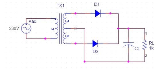
Two semiconductor diodes operating in complimentary mode are utilised in a full-wave rectifier. The AC input supply is fed into the primary coil P of a centre tap transformer. The two ends A and B of the second S of the transformer are connected to the p-ends of the diodes D1 and D2, respectively.
A load resistance RL is connected between the n-terminals of both diodes and the centre tapping O of the second transformer. By running the current through the load resistance RL, the DC output is produced.
Full Wave Bridge Rectifier:
One of the effective designs for a full-wave rectifier that makes use of four diodes in a bridge topology is the bridge rectifier circuit. A standard transformer is utilised in place of the centre tap transformer. The load resistor is connected across the remaining two diagonally different ends of the bridge, and the AC supply that has to be rectified is applied to the bridge’s diagonally different ends.


Center Tap Full-wave Rectifier:
A transformer with a secondary winding that is tapped at the centre point is used in this kind of rectifier circuit. Each diode in the circuit is connected so that it receives a half-cycle of the input AC voltage. While the other diode uses the lower half of the secondary winding for rectification, one diode employs the ac voltage visible on the upper half of the secondary winding. Because power is provided to both halves by the AC supply, this circuit has a high o/p and efficiency.


Controlled Rectifier:
Also adjustable is the voltage of the controlled rectifier. SCRs, MOSFETs, and IGBTs are used to control it. The two different kinds of controlled rectifiers are half wave and full wave rectifiers. The half-wave controlled rectifier is comparable to the half-wave uncontrolled rectifier, with the exception that an SCR is used in place of the diode.
Controlled rectifier types
There are two different kinds of controlled rectifiers: half-wave controlled rectifiers and full-wave controlled rectifiers.
Half Wave Controlled Rectifier:
A single Silicon Controlled Rectifier can be used to design the half-wave controller rectifier (SCR). The half-wave controlled rectifier has a similar construction to a half-wave uncontrolled rectifier, with the exception that we change the diode using an SCR.
A silicon-controlled rectifier cannot operate in reverse bias, therefore it will block the negative half cycle. When a pulse is applied to the gate terminal’s input, acting as a periodic pulse signal, the SCR will conduct current under a single state for the duration of the positive half cycle.
At each positive half cycle, this signal’s primary purpose is to activate the SCR.
The output voltage for the rectifier can be managed using this technique. Pulsating DC or voltage is the output of the silicon-controlled rectifier. With the aid of a capacitor that is linked parallel to the RL, these pulses are detachable.
Full Wave Controlled Rectifier:
Full-wave controlled rectifiers convert both the positive and negative half cycles of an AC signal into DC while controlling the o/p amplitude. Controlled full-wave rectifiers can be divided into two types, controlled bridge and controlled centre tapped, similar to how controlled and uncontrolled rectifiers are classified.
Controlled bridge rectifier:
An SCR bridge can replace the diode bridge in a controlled bridge rectifier using a setup akin to the bridge rectifier. A capacitor can be attached to the output end of the circuit to remove the ripples, resulting in a stable and smooth output.
Comparison of Various Types of Rectifier:
The tables below show comparisons between various rectifier types on several aspects.


Single Phase & Three Phase Types of Rectifiers:
A rectifier can be categorised based on how a particular input type operates. A rectifier is referred to be a single-phase rectifier if it has a single-phase input. Similar to this, a rectifier is referred to as a 3-phase rectifier if the input is three-phase. Four diodes can be used to create a single-phase bridge rectifier, while six diodes, arranged in a certain pattern to produce the desired output, can be used to design a three-phase rectifier. Based on the switching elements used in every type of rectifier, such as thyristors, diodes, etc., these rectifiers are classified as controlled or uncontrolled rectifiers.
Filter types used in various types of rectifiers:
Rectifier circuits produce DC, but when a bridge rectifier is used, we also get some AC in the output along with the DC. The output face of the rectifier is therefore equipped with various types of filters to reduce the AC component. Capacitors and inductors make up the majority of the filters utilised in rectifiers. Because parallel connections enable AC and prevent DC, they can be used to link a capacitor in a filter circuit. Any AC component will pass past the capacitor at the output in the direction of the ground, and we will obtain a small quantity of AC at the output. Since an inductor comprises inductive reactance, it is possible to link one in a filter circuit in series. This reactance opposes any changes and offers high impedance to AC and low impedance to DC since AC is a changing signal while DC remains constant. We can utilise an L-Section filter based on how a capacitor and inductor are arranged. One inductor is connected in series with a capacitor, which is connected in parallel, in this type of filter. The main components of a pi section filter are two capacitors connected in parallel by a series-connected inductor.
Rectifier’s Application:
Rectifiers are used in a number of applications, such as:
For electric welding, rectifiers are utilised to supply polarised voltage.
Half-wave rectifiers have a repellent effect on mosquitoes.
Half-wave rectifiers are utilised as signal peak detectors in AM radio.
Rectifiers are used in voltage multipliers, modulation, and demodulation.
Fixed access networks, wireless access networks, transmission networks, and workplace communication networks are all examples of applications for rectifier devices. Rectifiers effectively cut down on power use while supplying stable and dependable power to major suppliers. Because of this, before setting up or altering their system, every telecommunications business considers the many types of rectifiers.
Limitation of Rectifiers:
A rectifier has a few restrictions. Some of them consist of:
The output voltage/current from a full-wave rectifier is continuous in one direction, but the rectified voltage is produced as half-sinusoidal pulses.
Although unidirectional, the output voltage varies.
In order to create pure DC voltage output from a pulsing output with some AC ripple mixed in, we must filter out the AC ripple using an additional filter design.
YOU MAY READ THIS ALSO