Table of Contents
This Article establishes the minimum guidelines for E&I Technicians to perform the calibration of N2% analyzer. This document also enable E&I technicians to do primary level configuration and troubleshooting.
Scope and responsibility
This document is applicable for N2% analyzer (Siemens Calomat-6).
E&I Technicians are responsible to follow the steps as mentioned in this procedure.
E&I Manager and Instrumentation Engineers are responsible for the implementation of this procedure.
Competency Requirements
E&I Technicians must be trained and qualified to perform calibration of N2% analyzer.
Definition
The measuring principle is based on the different thermal conductivity of gases. The CALOMAT 6 sensor is a micromechanical-made Si chip with a measuring membrane and thin-film resistors. The resistors are adjusted on a constant temperature. This requires an current intensity depending on the sample gas thermal conductivity. Further this „coarse value“ is electronically processed and used to calculate the gas concentration. The sensor is located in a thermostatically-controlled stainless steel enclosure in order to prevent influences of ambient temperature changes. To prevent the influences by the sample gas changes, the sensor is not placed in the main flow.
These are used in a process industry for continuous measurement of N2% concentration. It is mandatory to calibrate them at regular intervals of time, so that there may not be any interlock failure.
References
- INSTRUCTION MANUAL (SIEMENS- CALOMAT-6)
Procedure requirement
SAFETY PRECAUTIONS
- Ensure that tools necessary for performing the task are being used.
- Wrong implementation of procedure/implementation without proper communication may lead to accidents or cause of plant trip.
SAMPLE REQUREMENT
For the best performance the flow, or pressure, supplied to the analyzer should be kept at a constant value for both normal sampling and for calibration gas input.
| Temperature | min. 0 … max. 50 °C |
| Sample gas humidity | non condensing < 90 % RH 3) |
| Condition | Oil free, non – condensing, filtered to 2μm |
| Sample Flow | (500 to 1500)ml/min |
| Sample gas pressure | 800…1100 hPa (absolute) |
| Vent | Each sensor outlet should be connected to a separate Atmospheric vent, free from any back-pressure.
(Consideration should be given to the toxicity and Asphyxiant nature of the sample gas when selecting a vent location) |
CAUTION
Do not exceed the rated flow or pressure as sensor damage may result
CALIBRATION FREQUENCY
4 Weeks
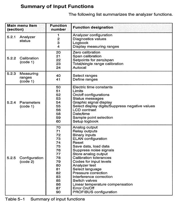
DISPLAY & FUNCTION LIST-

Calibration Procedure
Proper procedure is necessary to ensure the satisfactory operation.
- Ensure the Maximo Work order (print copy after WO released) is ready to perform the calibration on Analyser.
- Ensure the work permit/Maintenance request form to perform the calibration on Analyser.
- Put the Analyzer in CAL mode by changing the position of selector switch from Run mode to Cal mode in Analyzer panel.
- Connect the Zero Gas cylinder (Zero GR AR) and Span gas cylinder- (8 to 10)% N2, Bal AR and ensure respective sample tapings.
- Open Zero gas cylinder and regulate the set pressure at 0.5 barg (max.) and take it inline for analyser sampling.
- Set the flow in rotameter within the limit of (500 to 1500)ml/min.
- Now purge the analyzer for some time until the displayed value to be stable.
- If a considerable difference is observed in zero value then proceed with calibration. Enter in to Main Menu with help of Function key as shown in General Display above (General Display) and enter the code 222.
- Go to Function – 22 to change the target value for Zero Calibration. Once target value is entered select Function – 20 to proceed for Zero calibration. See Function List for further help
- Now press the corresponding Function key to Start Calibration.
- Zero calibration is in progress and wait for sometime till measured value equals to target value.
- Now Zero calibration is over.
- Release the pressure by moving the regulator knob anticlockwise and close the zero gas cylinder using cylinder key.
- Open the Span gas cylinder, set pressure to 0.5 barg (max.) and put span gas inline with the analyzer.
- Set the flow in Rotameter within the limits of 500 to 1500 ml/min.
- Purge the analyzer with same gas for some time and observe the value in the analyzer till it becomes stable.
- If a considerable difference is observed in span value then proceeds with calibration. Enter in to Main Menu with help of Function key as shown in General Display above (6.2 – General Display) and enter the code 222.
- Go to Function – 22 to change the target value for Span Calibration. Once target value is entered select Function – 21 to proceed for Span calibration. See Function List for further help.(Function List)
- Now press the corresponding Function key to Start Calibration.
- Span calibration is in progress and waits for sometime till measured value equals to target value.
- Span calibration is over.
- Release the line pressure by moving the regulator knob anticlockwise and close the span gas cylinder using cylinder key.
- Now take the process sample inline to the analyzer.
- Remove the analyzer from CAL mode
- Hand back the work permit & Close the work order.
Record Retention
- Check list for calibration of Analyzer and calibration record must be filled before & after the calibration.
- Calibration checklist must be signed by concern authority and it should be filed in preventive maintenance record.
- All calibration records should be kept for at least three years & after that it should be disposed off.
Read Also
- CO2 analyzer calibration | Servomex 4100 Series
- CO trace Analyzer Calibration-Siemens Ultramat-6
- Hydrocorbon anlyzer