Table of Contents
The vortex flow meter uses a principle called the von Karman. The Hungarian-American physicist Theodore von Karman was the first to describe the effect, where a nonlinear object (also known as a bluff body) is placed in the path of a fast-flowing stream, causing a fluid Optioally detaches from the object. On its two downstream sides, and, as the boundary layer separates and folds back on its own, vortices (also called vortices or eddies) are formed. He also noted that the distance between the vortices was constant and depended entirely on the size of the rock that formed it. On the side of the bluff body where the vortex is forming, the velocity of the fluid is greater and the pressure is lower. As the vortex moves downward, it increases in strength and size, and eventually separates or sheds itself. After this a vortex is formed on the other side of the bluff body. Alternating vortices are located at equal distances.
Vortex Flow Meter Working Principle
Vortex flow meters use a principle called the von Karmann effect to measure liquids, gases and vapors. In fluid dynamics, a Karman vortex lane is a repeating pattern of rotating (swirling) vortices caused by a process known as vortex drift (shedding). As water (or any other liquid, gas or vapor) flows through an obstacle, the fluid separates and creates an alternating differential pressure called a vortex.

How does it measure
Vortex flow meters measure by placing an obstacle (called a Bluff body) in the flow path, which creates vortexes of alternating differential pressure. These vortices cause a small sensor device to oscillate with a frequency directly proportional to the velocity of the moving fluid. The sensing element then converts the oscillation rate into an electrical signal, which is then converted into a quantitative velocity reading.
Two meters are available that may be classified as vortex meter. One is called a processing vortex meter or Swirlmeter, and the other uses the term vortex shedding.
1. Swirl Meter
The swirl meter operates on the principle of vortex precession. It is a digital volumetric device which has no moving part. It gives an output in the form of pulses whose frequencies are proportional to fluid flow rate. It consists of a fix set of swirl blades, unusually made of stainless steel, which introduce a spinning or swirling motion to the fluid at the inlet. At the down stream of a swirl blades there is a venturi – like contraction and expansion of the flow passage. A temperature sensor is placed at the down stream of the blades, which is heated by a constant electric current. At the exit of the meter-deswirl blades are fixed to leaving the meter, from down stream piping effects.
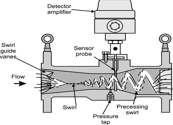
As the fluid passes through the fixed set of swirl blades at the inlet, a swirling (spinning) motion is imparted to it. In the area where expansion occurs, the swirling flow processes or oscillates at a frequency proportional to fluid flow rate. This precession of the fluid causes variation in temperature and resistance of the thermistor (sensor). The amount of heat extracted from the thermistor by passing fluid is dependent upon the fluid velocity. Consequently, each high velocity vortex passed the thermistor, changes the resistance and, since a constant current is applied, the resistance changes is converted in to voltage pulses which are amplified, filtered and transformed into constant amplitude high level pulses of square wave form. The frequencies of the pulses are measure by an electronic counter, which gives the flow rate of fluid. The swirl meter has an accuracy of +/- 0.75% within its linear operating range of +/- 1%. Its repeatability is +/- 0.25% and rangability 100:1. It is currently available in meter sizes from 25.4 to 152.4 mm. It is primarily used in gas applications, where a very much lower density results in a significantly lower pressure loss.
2. Vortex Shedding Flow Meter
The operation of vortex shedding flow meter is based on a phenomenon known as vortex shedding which occurs when a gas or liquid flows around a nonstream line (or blunt) object known as sluff body. When a fluid flows past an obstacle, boundary layers of slow moving fluid are formed along the outer surface of obstacle and the flow is unable to flow contours of the obstacle on its down stream side. Thus the flow layers are separated from the surface of the object, and a low pressure area is formed behind the object which causes the separated layers to get detached from the main stream of the fluid and roll them selves into eddies or vortices in the low pressure area. Each eddy on vortex 1st grows and gets detached or shade from alternate sides of the object. The frequencies at which the vortices are form is directly proportional to the fluid velocity.

As a vortex is shed from one side of the sluff body the fluid velocity on that side increases and the pressure decreases, and at the same time the velocity on the opposite side decreases pressure increases, thus causing a net pressure change across the sluff body. As the next vortex is shed from the opposite side of the sluff body, the inteire effect is reserved. Therefore the velocity and pressure distribution in the fluid around the sluff body change at the same frequency as the vortex shedding frequency. The changes in pressure of velocity is sensed by a flow sensitive detector which can be either a heat thermistor element or a spherical magnetic shuttle. The vortex shedding flow meters are available in the sizes from 50.8 to 152.4 mm. Its linearity is within +/- ½% and rangeability is 100:1. This meter has also no moving parts.
Vortex Meter Design
A vortex flowmeter is typically made of 316 stainless steel or Hastelloy® and consists of a bluff body, a vortex sensor assembly, and transmitter electronics, although the latter can also be mounted remotely. They are generally available in flange sizes from 1/2 inch to 12 inches. In size, the bluff body must have a width that is a large enough fraction of the pipe diameter to allow the entire flow to participate in shedding. Second, regardless of the flow rate, the bluff body must have raised edges on the upstream face to correct the lines of flow separation. Third, the length of the bluff body in the direction of flow must be a fixed multiple of the width of the bluff body.
Most Vortex flow meters use piezoelectric or capacitance-type sensors to detect pressure oscillations around the bluff body. These detectors respond to pressure oscillation with a low voltage output signal that has the same frequency as the oscillation. Such sensors are modular, cheap, easy to replace, and can operate over a wide range of temperature ranges – from cryogenic liquids to superheated steam. Sensors can be located inside or outside the meter body. Wet sensors are directly stressed by vortex pressure fluctuations and are enclosed in rigid cases to withstand corrosion and corrosion impacts. External sensors, typically piezoelectric strain gauges, sense vortex shedding indirectly through a force applied to the shader bar. External sensors are preferred over highly erosive/corrosive applications to reduce maintenance costs, while internal sensors provide better rangeability (better low flow sensitivity). They are also less sensitive to pipe vibrations. Electronics housings are typically rated explosion- and weatherproof, and contain an electronic transmitter module, termination connections, and optionally a flow-rate indicator and/or totalizer.
Key Elements to Consider Before Choosing a Vortex Flow Meter
- What is the liquid being measured for?
- Pressure Maxium and Min
- Floret Range
- Fluid Temperature
- Fluid Density Range
- Viscosity Range
- Pipe Size
- Maximum allowable pressure drop
- Pipe Schedule or Wall Thickness
- Pipe Material
- Nearest Upstream Obstacle
Vortex Flow meter Advantage
- Has an excellent rangeability.
- Handles a wide verity of chemicals, including slurries, liquids with entrained particles and viscous materials.
- Have no moving parts.
- Relatively immune to density, temperature, pressure and viscosity variations within the linear range
- Very low pressure drop
- Has good response speed
Vortex Flow meter Dis-advantage
- High cost
- Not available over 200 mm size
- Upper temperature limit is 2040c
- In line mounting required.
Read Also