Table of Contents
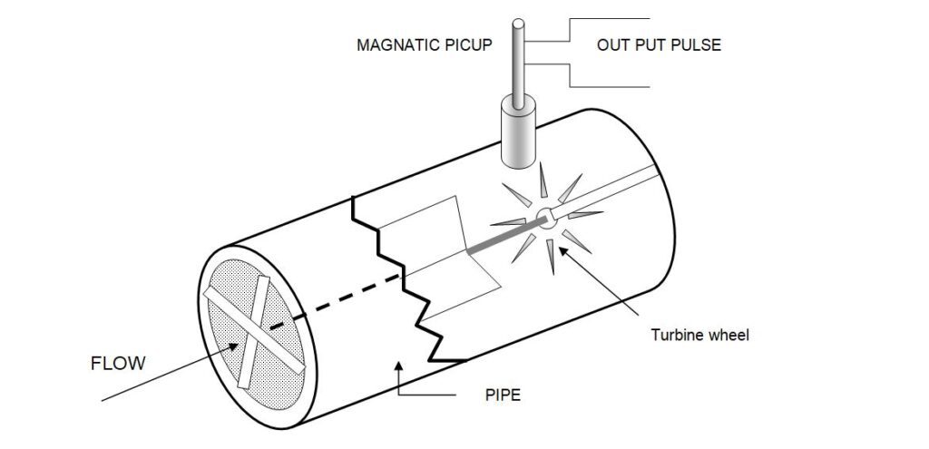
A turbine flow meter is used for the measurement of liquid, gas, and very low flow rates. It works on the basic principle of a turbine. It consists of a multi-blade rotor (turbine wheel) mounted at right angles to the axis of the flowing fluid. The rotor is supported on the shaft by the ball or sleeve bearings which are placed in the flow meter by the shaft support section. The rotor is free to rotate on-axis. The flowing fluid hits the blades of the turbine, imparting a force to the blade surface, which causes the rotor to spin. At a constant rotational speed, the rotor speed is directly proportional to the fluid velocity, and therefore to the volumetric flow rate. The rotation speed is monitored in most meters by a magnetic pickup coil, which is fitted on the outside of the meter housing. But internal to the fluid channel. As each rotor blade passes through the magnetic pickup coil, it generates a voltage pulse which is a measure of flow rate, and the total number of pulses gives a measure of total flux. Electrical voltage pulses can be aggregated, differentiated and manipulated by digital techniques to provide the zero error characteristics of digital handling from the pulse generator to the final read out. The K. factor (i.e. the number of pulses generated per gallon of flow) is given as,
K= T kF/Q
Where:
K= Pulse per volume unit. T k = A time constant in min.
Q= A volumetric flow rate in gpm. F= frequency in Hz
Turbine flow meters provide very accurate flow measurements over a wide flow range. The accuracy range is from +/-1/4 to +/- 1/2%, and repeatability is excellent, ranging from +/- 0.25% to +/- 0.02%. Generally Range-ability of Turbine Meter Between 10:1 and 20:1 is considered, although in low flow ranges, it is often less than 10:1. Military type turbine meters have achieved a range-ability of over 100:1. Turbine meters are available in sizes from 6.35 to 650 mm and have liquid flows ranging from 0.1 to 50,000 gallons per minute.
Turbine meters are widely used for military applications. They are particularly useful in blending systems for the petroleum industry. They are effective in aerospace and airborne applications for energy-fueled and cryogenic (liquid oxygen and nitrogen) flow measurements.
What is the k factor in a turbine flow meter?
The K-factor is a prime coefficient that represents the number of pulses per unit volume or mass of the medium. This constant value includes the main characteristics of the substance and the pipe (viscosity, temperature, diameter, etc.).
This is necessary for the correct display of values in measurement systems. After calibration, this coefficient is indicated in the product certificate.
Turbine Flow Meter Calibration
Calibration of the device is carried out in laboratory conditions on water.
If the device must be used in a viscous medium (2-300 cSt, Centistoke), a fluid with properties similar to the working medium is taken for calibration.
As a result, each objective and medium is assigned its own k-factor. Sometimes, manufacturers add ready-made universal viscosity charts to their tool kits for calibration. Using them, the user can quickly determine the previously calculated K-factor for various substances.
How to Install Turbine Flow Meter? Installation Guidelines
- The turbine flow meter is installed only on straight sections or vertical and horizontal pipelines.
- On its housing there is an arrow indicating the desired flow direction.
- The length of the straight section must be at least 10 pipe diameters before a single-turbine device, and at least 5 diameters thereafter. Dual turbine units can be installed on straight sections of short distances.
- On a vertical pipeline, it is best to install the flowmeter so that the fluid flow is directed from top to bottom. In this case, air bubbles accidentally entering the device will quickly leave it.
- If the device needs to work with contaminated media, it is worth mounting and additional filters to avoid damage to the structure by solid particles.
Size and selection
Turbine meters should be sized such that the expected average flow is between 60% to 75% of the meter’s maximum capacity. If the pipe size is large (flow velocity is less than 1 ft/s), one should select Hall-effect pick-up and use a meter smaller than the line size. Flow velocities less than 1 ft/s may be insufficient, while velocities greater than 10 ft/s may result in excessive wear. Most turbine meters are designed for a maximum velocity of 30 ft/s.
Turbine flow meter size should be between 3 to 5 side pressure drop at maximum flow. Since the pressure drop increases with the square of the flow rate, reducing the meter to the next smaller size will increase the pressure drop significantly.
Viscosity affects the accuracy and linearity of the turbine meter. As a result, it’s critical to calibrate the metre for the fluid it’ll be measuring. Repeatability is usually not greatly affected by changes in viscosity, and turbine meters are often used to control the flow of viscous fluids.When the Reynolds number is greater than 4,000 but less than or equal to 20,000, turbine metres operate well.
Because it affects viscosity, temperature variation can also adversely affect accuracy and must be compensated for or controlled for. The operating temperature of turbine meters ranges from -200 to 450 °C (-328 to 840 °F).
Density changes don’t affect turbine meters much. At low-density fluids (Sg < 0.7), the minimum flow rate increases due to the reduced torque, but the accuracy of the meter is usually not affected.
Precautions for Turbine Flow Meter
Turbine meters are less accurate at lower flow rates due to rotor/bearing drag which slows down the rotor. Be sure to operate these flow meters above about 5 percent of maximum flow. Turbine flow meters should not be operated at high velocities as premature bearing wear and/or damage may occur.
Be careful when measuring non-lubricating fluids as bearing wear can cause the flow meter to become inaccurate and fail. In some applications, bearing replacement may need to be performed regularly and increase maintenance costs.
Application in dirty liquids should generally be avoided to reduce the potential for flow meter wear and bearing damage. In short, turbine flow meters are moving parts that are subject to degradation over time and use.
Sudden transitions from gas flow to liquid flow should be avoided as they may mechanically pressurize the flow meter, reduce accuracy, and/or damage the flow meter. These conditions usually occur when filling pipes and under slug flow conditions. Two-stage flow conditions can also cause a turbine flow meter to measure incorrectly.
Advantages of Turbine Flow Meter
1. Good accuracy
2. Provides excellent repeatability and range-ability.
3. Fairly low pressure drop.
4. Easy to install and maintain.
5. Good temperature and pressure rating.
6. Viscosity variation can be compensated for.
Disadvantages of Turbine Flow Meter
1. High cost
2. Limited use for slurry applications.
3. Problems caused by non-lubricating fluid.
Read Also
- Flowmeter
- Orifice meter
- Different Type Flow element
- Different types of flow meters | flow meter type