Table of Contents
Principle of operation:-
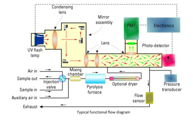
Sulfur Analyzer is based on the principle that SO2 molecules absorb UV light and become excited at one wavelength, then decay to a lower energy state emitting UV light at a different wavelength. Specifically,

The sample inlet bulkhead draws the sample into the analyzer. The sample is mixed with air and passes through a pyrolyzer furnace that oxidizes the sulphur molecules in the sample to produce SO2. The sample then flows into the fluorescence chamber where pulsating UV light excites the SO2 molecules. The condensing lens focuses the pulsating UV light onto a mirror assembly. The mirror assembly contains four selective mirrors that reflect only the wavelengths that excite SO2 molecules. As the excited SO2 molecules decay to lower energy states, they emit UV light that is proportional to the total sulfur concentration in the sample. The bandpass filter allows only the wavelengths emitted by the excited SO2 molecules to reach the PMT, which detects the UV light emission. The photo detector, located at the back of the fluorescence chamber, continuously monitors the pulsating UV light source to provide compensation for fluctuations in the UV light source. The measured SO2 concentration (representing total sulfur in the sample) is processed, displayed on the front panel display, and sent to the analog outputs.
PUVF detector:-
The PUVF detector includes and controls the following:
- UV pulsed light and associated systems
- Reaction chamber temperature control
- Digitizing of PMT signal
- Smoothing of measurement signal using moving average.
Pyrolyzer:-
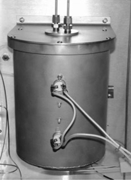
Measuring total sulfur with the PUVF detection method requires the conversion of all sulfur compounds in the sample to SO2. This is typically accomplished with the pyrolyzer, an electrically heated furnace designed by Thermo Fisher Scientific. The pyrolyzer typically operates at a temperature of 1100°C (2012°F) to oxidize sulfur without need for a catalyst.
Dryer:-
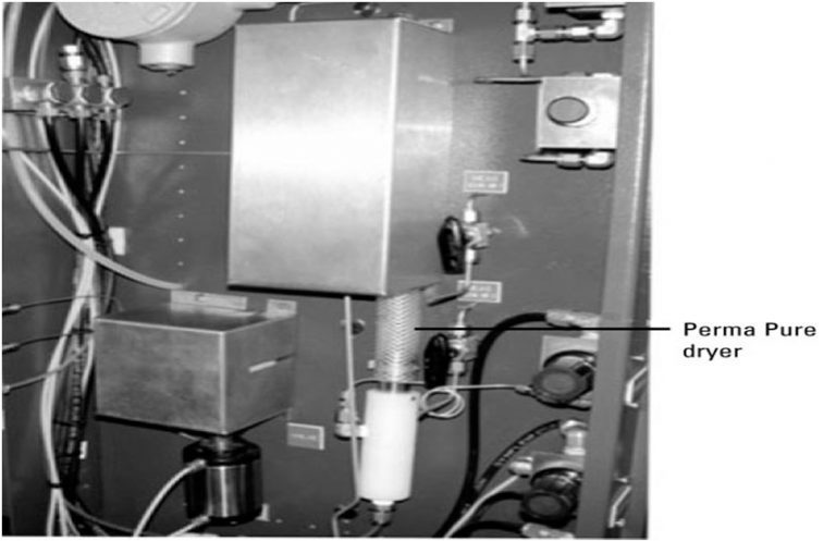
The optional Perma Pure dryer removes moisture from the sample prior to its entry into the PUVF detector. A filter is positioned before the dryer to protect it from impurities. Dryer tubing consists of multiple small tubes encased in a large outer tube. Air circulates through the outer tube with sample passing through the inner tube. Moisture passes from the sample through the tubing where it is carried to the condensate drain by the airflow in the outer tube.
Mixing Chamber:-
The mixing chamber mixes the gases and permits the sample to vaporize to a gaseous state before entering the pyrolyzer.

Injection Valve:-
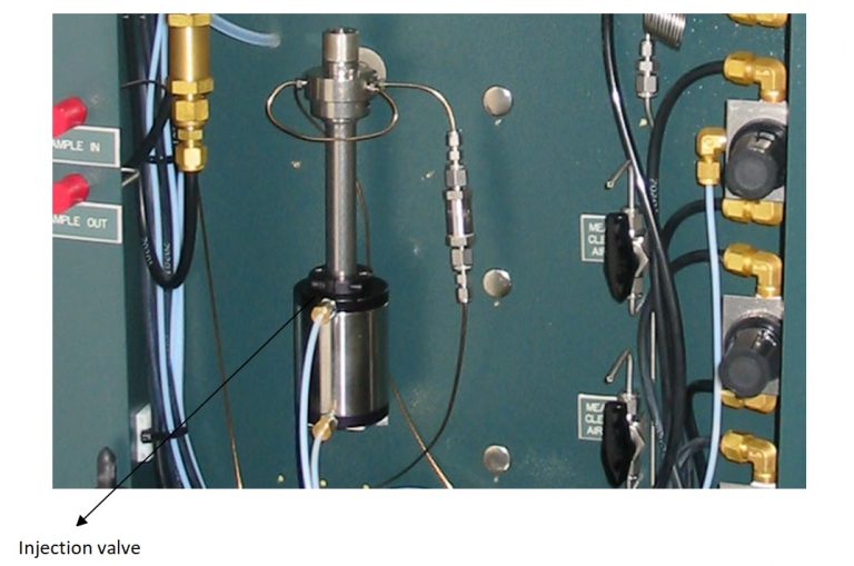
The injection valve periodically injects precisely measured quantities of the sample stream into controlled carrier airflow. An auxiliary airflow is added to this sample and air mixture. The sample then passes to the mixing chamber where it vaporizes (if necessary) and is thoroughly mixed with the air.
Read Also:-
Related Search:-

Level Switches working
Level Switches working

Density Measurement
Density Measurement

Capacitive level switch
Capacitive level switch

Thermopile
Thermopile

Interview Questions
Interview Questions

How to control boiler drum level
How to control boiler drum level