Table of Contents
Introduction-
The most common and widespread technology in EM field theory for detecting the magnetic field is the Hall-Effect method among the various sensing technologies. Based on the Hall-effect principle, there are numerous Hall-effect sensors and transducers found in a wide variety of applications in measurement which are most commonly used for sensing proximity, distance, speed, current and position etc.
A Hall Effect sensor (or simply named as Hall sensor) is a device which detects the presence and magnitude of a magnetic field around it using Hall Effect principle. Hall Sensors are basically type of magnetic sensors that are designed to respond to a wide range of positive and negative magnetic fields in different applications. Since magnetic field has two important characteristics magnetic flux density (B) and polarity (position N or S pole), the output voltage of a Hall sensor is directly proportional to the strength of the magnetic field (B). Here generated voltage is transverse and called as Hall Voltage (VH).
A typical Hall Effect sensor diagram is shown below-
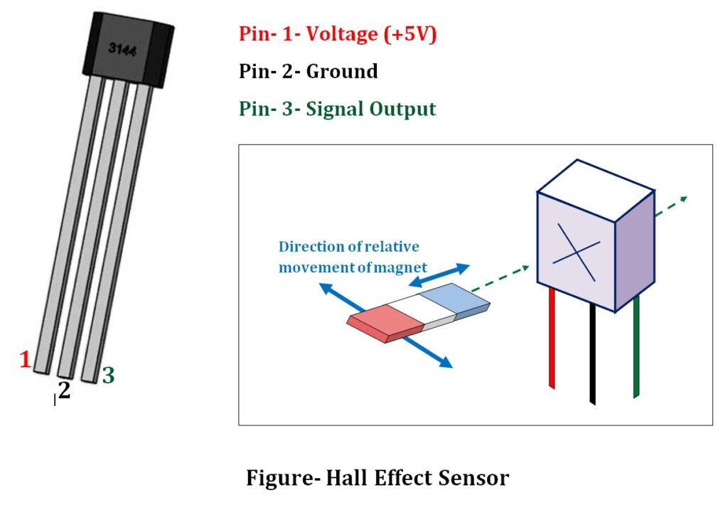
Hall Effect sensor working principle
Hall Sensors are based on Hall Effect principle and the Hall Effect principle states that when a current-carrying conductor or a semiconductor is placed in a perpendicular magnetic field, a transverse voltage is produced or measured at the right angle to the current path. This effect of obtaining a measurable voltage across material is known as the Hall Effect. And this transverse voltage is referred as Hall Voltage. To explain theory behind, a diagram is shown below-
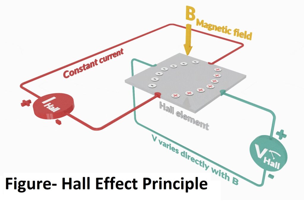
When a hall element/ hall sensor is connected to a circuit containing a DC supply, a current begins to flow and charge carriers follow an approximately straight, ‘line of sight’. To detect physical quantities such as position, speed, current, temperature, etc, magnetic system is used to convert physical quantities into change in magnetic field. When there is change in magnetic field which is a perpendicular component to the current flow, the magnetic field of the charge carriers gets distorted. This produces a disturbance in the direct flow of charge carriers. Thus a Lorentz force arises that is perpendicular to both the ‘line of sight’ path and the applied magnetic field. This establishes an electric field that opposes the migration of further charge carriers and so a steady electric potential is established as result of the charge flowing for longer duration. This is called as Hall voltage (VH).
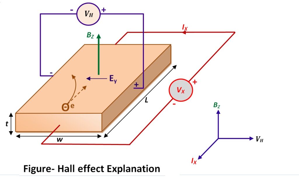
Hall voltage formula –
The Hall voltage (VH) is defined as-

From the formula, it is clear that the output voltage of a Hall sensor or transducer is directly proportional to the strength of the magnetic field. So hall effect transducer can be used to measure magnetic field strength.
Hall Effect sensor circuit
Basically Hall-effect sensor converts the magnetic field into electrical signal. There are various types of Hall sensor IC available for various applications such as to detect the motion, position, speed, change in field strength of an electromagnet, a permanent magnet, or a ferromagnetic material etc. hall sensor can be used for switch application too. A block diagram of Hall Sensor is mentioned below-

A circuit diagram for Hall Effect sensor IC 3144 is shown below-

Types of Hall Effect sensors
Based on types of output from Hall Sensor, there are two categories exist-
- Linear Hall Sensor
- Digital Hall Sensor
Linear Hall Effect Sensors are basically analog hall sensor. Here output of the hall sensor is analog and proportional to the strength of magnetic field (B). So analog signal (output) increases with stronger magnetic field and decreases when magnetic field is getting weak.
Digital Hall Effect sensors are basically providing digital output in response of change in magnetic field by converting hall voltage into digital form. They use Schmitt trigger circuits as bi-stable circuit that steadily increases and decreases the output when the voltage rises and falls to its threshold values. Digital hall sensors can be used for speed monitoring, proximity detection, object counting, and a wide range of switching applications etc. A diagram for digital Hall Sensor is shown below-

Hall Probe-
A Hall probe is a device that uses a calibrated Hall sensor to measure the strength of a magnetic field. That’s why the result from a Hall probe is dependent on the orientation, as well as the position, of the probe.
The key factor determining the sensitivity of Hall sensors is higher electron mobility. There are several materials which are especially suitable for Hall Effect sensors as shown below-
- Gallium Arsenide (GaAs)
- Indium Arsenide (InAs)
- Indium Phosphide (InP)
- Indium Antimonide (InSb)
- Graphene
Hall Effect sensor applications
- In BLDC (Brushless direct current) technology uses
- In BLDC motor (BLDC fan)
- for internal combustion engine ignition timing
- in mobile phones and tablets
- In RPM sensors such as tachometers
- In encoders
- In anti-lock braking systems (in automobile industries)
- In Switching application
- In Position and proximity Sensors
- In Current Sensors
- In computers as disk drive index sensors, in keyboards.
- They are also used for measurement of flow, level, pressure and temperature also, etc.
Hall sensor manufacturer
- Allegro Microsystems (Models- A3141, A3142, A3143, A3144, A1101, A1102, A1103, A1104)
- Honeywell Hall Sensor (Model- SS39ET, SS49E, SS59ET Series)
- Carter Microwave (Model- OH137)
Interfacing Hall Effect Sensor Arduino
A circuit diagrams for interfacing Hall Sensor with Arduino Uno with hall Sensor is shown below-

Related Search:-