Table of Contents
Fundamental of 4-20 mA Current Loops
In process control, there are different types of infinite process inputs. Thermocouples and RTDs provide direct temperature reading while digital signals such as Modbus provide exacting control over process variables and display. Analog signals, where information about the process is transmitted via varying amounts of voltage or current, are the main type of input in industries requiring process control today. Out of all the important signals used to transmit process parameter in the industry, 4 to 20 mA signal is the most important.
As major as the 4-20 mA current loops standard has become in the process control industry, many do not understand the fundamentals of its setup and use.
A Little Bit of History
First appearing in the 1950’s with the advent of electrical and electronic controls, the 4-20mA signal standard reigns as one of the most popular mediums for signal transmission and electronic control in industrial environments.
Prior to the widespread adoption of electrical and electronic controls, Industries often used pneumatic control systems. Air pressure at 3psi served as the “live-zero” and 15psi represented 100%. In this way, the more modern 4-20mA signal standard emulated the earlier 3-15psi pneumatic controls. Any pressure below 3psi was considered “dead zero” and an alarm condition. Some installations still use pneumatic control today. Modern I/P converters (current-to-pressure transducers) are available to convert the 4-20 mA current loops to common pneumatic ranges, such as 3-15psi. In two-wire 4-20mA control loops, we use 2-wire transmitters to convert various process signals representing flow, speed, position, level, temperature, pressure, strain, pH, etc., to 4-20mA DC for the purpose of transmitting the signal over some distance with little or no loss of signal.
The Basics of 4-20mA Current Loops
In simple language we understand 2 wire loop by a triangle. From the triangle, I can quickly identify the three common components of a current loop, how they are wired together, and even the direction of current flow.

Each side of the triangle represents a component of the current loop. The vertices of the triangle represent a wired connection between these components. For reference, I also place a positive/plus sign on the “peak” of the triangle. I will also use the first three letters of “TRIangle” to identify the principle components. Accepting the convention that current flow will move from the supply positive to and return to the supply negative, I see that current moves counter-clockwise in my symbolic current loop.


Transmitter is not the source of current, but simply regulates the flow and magnitude of the current through it. The current is sourced by the power supply, flows in controlled function through the transmitter, then into the receiver, and returns to the power supply. The current flowing through the receiver produces a voltage that is easily measured by the analog input of a controller or monitoring device.Now we will understand with a standard DC circuit:-
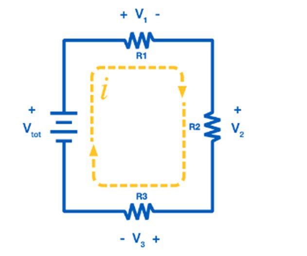


Consider the simple DC circuit above, consisting of a power supply and three loads. A current loop requires voltage to drive the current. This is provided by the power supply, with the voltage of the supply labeled as Vtot. Current then flows through the loop, passing through each load. The voltage drop at each load can be calculated from Ohm’s Law. The voltage drop V1 across R1 is
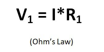


Every element in the loop either provides voltage or has a voltage drop. However, the current, “I” is the same everywhere in the loop. This is the critical principle of the 4-20 mA current loops. Current is the same in all places throughout the loop.
To help us to understand the operation of a two-wire current loop, let’s consider each element of the current loop separately:
1. Sensor
A sensor typically measures temperature, humidity, flow, level or pressure. The technology that goes into the sensor will vary and depending on what exactly it is intended to measure.
2. Transmitter
Second, whatever the sensor is monitoring, there needs to be a way to convert its measurement into a current signal, between 4 to 20 mA. If a sensor is measuring the height of a 50 ft tank, the transmitter will need to translate 0 feet as the tank being empty and then transmit a 4 mA signal. Conversely, it will translate 50 feet as the tank being full and will then transmit a 20mA signal. If the tank is half full the transmitter will transmitt 12 mA. The transmitter typically uses 4mA output to represent 0% level , and 20mA output to represent 100% of level as shown in Figure below:


3. Power Supply:
The current loop uses DC power because the magnitude of the current represents the signal level that is being transmitted. For 4-20mA current loops with 2-wire transmitters, the most common loop power supply voltage is 24V DC, but there are also instances of 12V, 15V, and 36V DC. Some older systems use higher voltages. But the most important thing to remember about the power supply is that it must be set to a level that is greater than the sum of the minimum voltage required to operate the Transmitter, plus the voltage drop in the Receiver, and for long transmission distances, the voltage drop in the wire. Calculating this drop must also consider the maximum level of current that can flow in the 4-20mA current loop.
4. Loop
In addition to an adequate VDC supply, there also needs to be a loop, which refers to the actual wire connecting the sensor to the device receiving the 4-20 mA signal and then back to the transmitter. The current signal on the loop is regulated by the transmitter according to the sensor’s measurement. Wiring in loop can be 2 wire, 3 wire, and 4 wire with source and sink I/O configuration.
5. Receiver
Finally, at someplace in the loop there will be a device which can receive and interpret the current signal. This current signal must be translated into units that can be easily understood by operators, such as the feet of liquid in a tank or the degrees Celsius of a liquid. This device also needs to either display the information received (for monitoring purposes) or automatically do something with that information. Digital displays, controllers, actuators, and valves are common devices to incorporate into the loop.
These components are all it takes to complete a 4-20 mA current loop. The sensor measures a process variable, the transmitter translates that measurement into a current signal, the signal travels through a wire loop to a receiver, and the receiver displays or performs an action with that signal.
Read Also:-
What is source and sink concept?
2-wire,3-wire and 4-wire transmitter wiring
Related Search:-


Level Switches working
Level Switches working


Vibration Switch
Vibration Switch


Vibrating rod Type level Switch
Vibrating rod Type level Switch


Filter Regulator Lubricator
Filter Regulator Lubricator
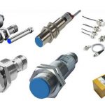


Proximity Switch
Proximity Switch


Why 4 to 20 mA used?
Why 4 to 20 mA used?