Table of Contents
The primary purpose of process instrumentation is automatic control of operating process units. Without process control, it is impossible and impractical to operate process units. Their large size and complex design depend entirely on the proficiency of process instrumentation.
Automatic Process Control is the control of measured process variables for the safe and economical operation of process equipment and includes the measurement, transmission, and presentation of these variables. Although automatic control may be accomplished locally near the operating equipment, most is done remotely in centralized control rooms. Therefore, process instrumentation is generally considered as the centralized automatic control systems found in fertilizer and chemical processing industries.
Every automatic process controller is given two pieces of information: measurement and set-point. These may be pneumatic or electronic signals, or they may be mechanical movements of a link and lever arrangement. The controller reacts to the difference in value of these two signals or movements and produces an output signal to eliminate that difference. As long as the difference exists, the controller will try to eliminate it by increasing or decreasing its output signal (actually this is not true of proportional only controllers, proportional only controllers will eliminate deviation only when the set point and proportional band adjustment are at specific values).
When measurement and set point are equal, the condition of the controller is static and its output is unchanged. Any deviation of measurement from set point will cause the controller to react by changing its output signal.
An automatic process controller must eliminate the deviation of measurement from set point in a way least upsetting to the process and the operating equipment. Therefore it must react to the size, direction, rate of change, and duration of the deviation, because the dynamic characteristics of each process are unique and difficult to predict, automatic controllers are designed with adjustable control mode settings with these adjustments each controller, after installation, can be tuned to handle the dynamic characteristics of the specific process producing its measured variable.
Explanation of closed control loop
For closed loop control loop see the slide-CLP. Which is self explanatory?
 Closed loop control loop has mainly following components
Primary Element
It is the device used to measure the value of the process variable and convert it into a usable form which can further be converted into usable electrical or pneumatic signal. For example orifice plates are used to develop the differential pressure DP which is the signal proportional to the flow in the Process line. primary elements may be of many types .some of them are given in the tabular form as below:-
|
SN |
VARIABLE | PRIMARY ELEMENT USED TO MEASURE |
| 1 | Flow | Orifice plate, annubar, venturi tube, flow nozzle etc. |
| 2 | Level | Air purged thru tube and back pressure sensed by transmitters, pressure head indicators, radioactive, ultrasonic , displacers, floats ,capacitors etc. |
| 3 | Temperature
|
Thermocouple, resistance temperature detectors(RTD),Infrared sensors etc. |
| 4 | Vibrations | Inductive pickup coils. |
Measured Process Signal
It is the electrical or pneumatic signal coming out of the primary transducer in the form of volt, pressure of different range etc.. this is converted into 4 to 20 mA or 3 to 15 psig and fed directly to the controller.
| SN | VARIABLE | MEASURED PROCESS SIGNAL |
| 1 | Flow | Differential pressure |
| 2 | Pressure | Direct pressure |
| 3 | Level | Pressure,differential pressure, back pressure etc. |
Transmitter
The primary transducers generate a signal equivalent to the variable being measure which are converted into suitable signal by transmitters to be fed into the feedback module of the controller. Internationally all the transmitters provides 4 to 20 mA output which can be accepted by all types of input devices like controllers, indicators, recorders ,PLC’s etc. These are very important part of the total closed loop control loop as Quality of control action is mainly dependent on the quality of process variable measurement which is done by primary elements and transmitters only. Now a days transmitters for all types of variables are available in the market. We are even getting combined package of primary element and transmitters together for many variables like pressure, level, weight etc. which directly mounted on the vessel provides 4 to 20 mA outputs.


Feed back Module(Inside Controller)
Transmitter output is fed to the input of the controller which posses a feedback module. Feedback module manipulates the transmitter signal in such a way so as to feed it negatively to the error generator. Stability of process control depends on the gain of the feedback module and PID module.


Error Deviation Generator (inside controller)
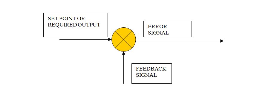
Controller is programmed with a required signal which is called SET POINT the difference between set point and signal (equivalent to process signal ) coming out of the feedback module process output is the output which generates the ERROR SIGNAL .


Output Going to Control the Process (inside controller)
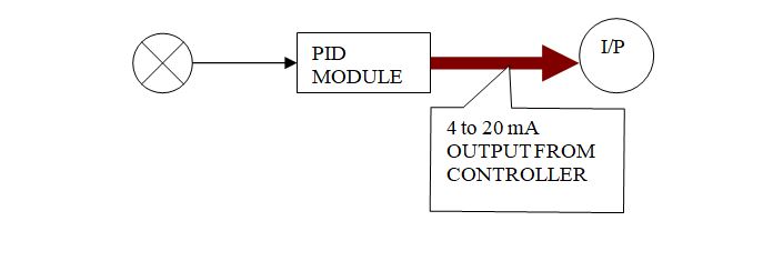
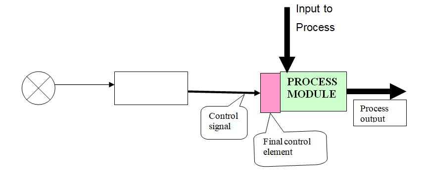
The above generated controller output goes to the current to pneumatic converters called I/P converters. These provide pneumatic output to control the final control element which are generally control valves.


Process Module
The main processes which are subjected to be controlled they may be heat exchangers for temperature control, sumps or condensers for level control, or instrument air receivers for pressure control. Whole control theory and strategies are applied to control their output. Correct and quality control system assures perfection in the output received from the process modules.


Read Also
- Controllers | Configuration of a controller
- Electronic Control System
- Pneumatic Control System
- Hydraulic Control System
- Comparison of Pneumatic and Electronic Control Systems