In a hydraulic control system ,pressurized and filtered clean oil is supplied to the controlling Element . As the value of the measured variable changes ,the hydraulic output of the controlling element changes with it. A nozzle mechanism provides the means of controlling the hydraulic output. Essentially the hydraulic controller resembles the pneumatic except that the system must remain completely closed. In place of the flapper nozzle and air relay of the pneumatic controller. Jet pipe and piston or four way valves are used.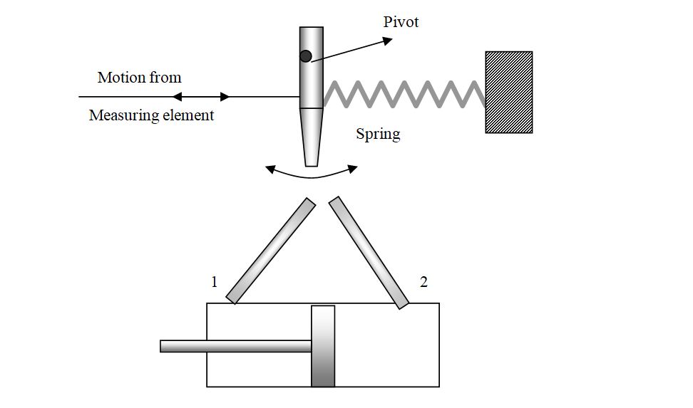 The jet pipe resembles the pneumatic nozzle ; it directs a fluid stream into either of two receiving chambers of a double acting cylinder. When the jet pipe ,shown in fig… is moved to the left by the measured variable, more fluid enters chamber 1 than enters chamber 2 . This causes the pressure in chamber 1 to increase ,moving the piston to the right. The piston movement can be used to position a final element. The four way valves can be used instead of a jet pipe in the same manner.

Hydraulic Control, Turbine governor controls, etc. Such systems may employ proportional position only but this after creates offset. Stabilization is, therefore obtained by integral action. The schematic of a system employing a nozzle and orifice pair is shown in fig… below..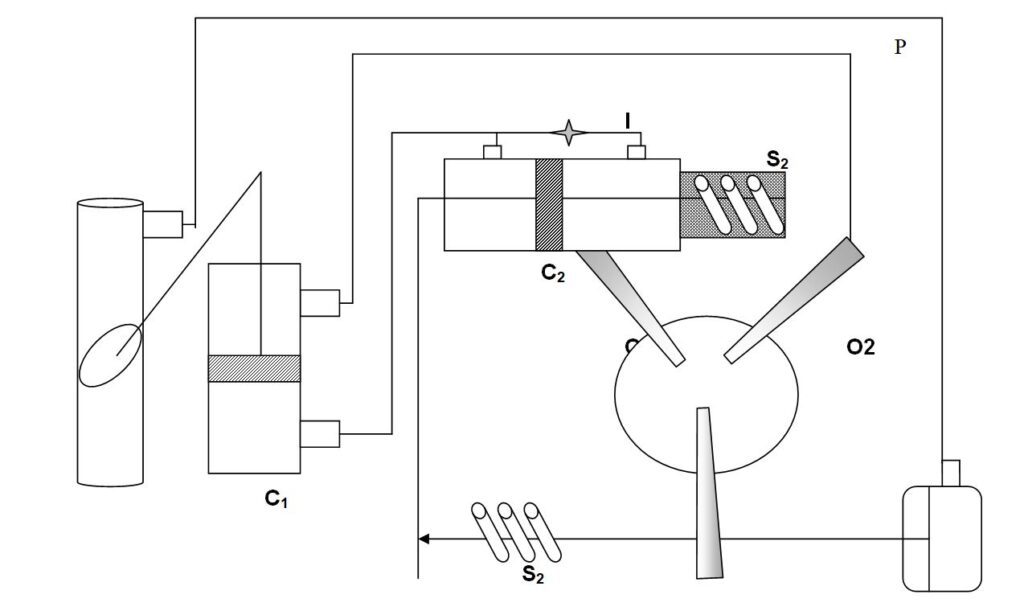
With the change in pressure P diaphragm D shifts, moving nozzle N against spring S2 from zero condition , thereby creating an unbalanced supply of oil to orifices O1 & O2. If N moves to the left , supply to O1 is more than to O2 , the piston in C2 moves left , applying more pressure to the bottom part of cylinder C1 and pushing the piston up, which in turn throttles the butterfly valve. Direct proportional action is obtained through
the movement of piston in C2, spring S1 acting against the given setting; the lever against fulcrum F pushes the spring and thereby also the nozzle for balancing. However, unless the needle valve I is used for integral action, proper positioning will not be obtained and offset will result. The action stops when the position in C2 assumes mid-position; this means that the pressure on both sides is equal, I ceases to act and spring S1 helps to attain this position. Fulcrum F is moved to give more or less proportional gain ( PB ) and I is set for a repeat rate of the reset action.
Read Also
- Comparison of Pneumatic and Electronic Control Systems
- Electronic Control System
- Pneumatic Control System
- Control System | Type of Control Loop | Open loop | Close Loop