Table of Contents
Definition and diagram
Hydraulic actuator is such actuator which uses hydraulic signal or fluid (mostly oil) pressure to move a valve mechanism i.e. controlled hydraulic oil pressure is used to force a piston. Here a piston is preferred rather than a diaphragm against mechanical spring or balancing pressure which results mechanical action or valve stroke. Hydraulic fluid (oil) used for actuators are non-compressible in nature & its lubricating property helps to overcome the friction problem of piston-type actuators. Hydraulic oil pressure can be generated by an electric motor driven pump connected through an oil reservoir. The oil pressure used to drive piston can be used up to 400 bar (6000 PSI). Hydraulic actuators are used for extremely large force application. A hydraulic actuator diagram is given below-

Hydraulic actuator working
Hydraulic actuator working is based on Pascal’s law (also known as Pascal’s principle) which states that when a change in pressure is applied to an enclosed fluid, it is transmitted undiminished to all portions of the fluid and to the walls of its container. So if a seal tight piston is kept inside a cylindrical container, fluid under pressure pushes container walls as well as move piston outside. Suppose, if pressure (P) is applied to a cross section area (A), then the resultant force (F) due to an applied pressure will be:

Now, it is clear evident that force generated depends on the pressure and area both. So if certain fluid pressure is applied in a smaller area will produce smaller force and larger pressure, comparatively produces larger force. In this way, the applied pressure at a certain point is used to generate very large forces and this principle is utilized by hydraulic systems.
Hydraulic actuation system
Hydraulic actuation system basically provides complete arrangement of fluid pressurized system in a safe and reliable manner to enable hydraulic actuator operation. It can be divided into 3 major sub-categories-
- Hydraulic power unit
- hydraulic actuator assembly
- Control function
Hydraulic power unit provides pressurized fluid (oil) using pump, driven by an electrical motor, and contains an accumulator to use for emergency operations of actuator to move 1 to 2 stroke full movement, when pump unit not able to operate due to supply fail or pump fail etc.
Hydraulic actuator assembly is normally a piston cylinder assembly used to operate connected load. Control function provides precise regulation of load as well as emergency trip (ESD) operation.
Control function can be achieved by using I to H converter for proportional control action and using solenoid valves for ESD function.
A simple block diagram of hydraulic system & actuator is given below-

From the diagram, a basic requirement of hydraulic actuation system is given below-
- Oil reservoir
- Oil temperature monitoring system
- Heater
- Electric Motor driven pump
- Pressure monitoring system at different stages
- Relief valves
- Check Valves
- Particle Filter & moisture absorbing filter
- Hydraulic accumulator
- Manual valves, solenoid valve
- I/H converter
- High pressure hoses/ tubing
- Piston cylinder assembly (Actuator)
Some points to remember-
- Mostly Hydraulic actuators are designed for Fail safe position to Lock actuator & fail close or fail open position is achieved by ESD trip function.
- It should be noted that fluid pressure release cannot be done in open atmosphere so fluid return to reservoir path is provided additionally.
- Hydraulic actuators are designed for both linear action & as well as rotary action too.
- Since fluid pressure is very high so periodic inspection of tubing, hoses is highly recommended at regular interval.
Types of hydraulic actuators
There are mainly 2 methods of categorization as mentioned below-

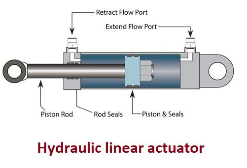
Hydraulic linear actuator
When hydraulic actuators deliver linear motion in response of controlled signal pressure applied to it, it is referred as linear hydraulic actuator. Mostly such actuators are used for slide valve, gate valve, damper, louver applications to regulate fluid flow. In such actuator, piston actuator stem is directly connected to load. A diagram of hydraulic linear actuator is shown below-
Hydraulic rotary actuator
When hydraulic actuators deliver rotary motion in response of controlled oil pressure applied to it, it is referred as hydraulic rotary actuator. Such actuator uses a pressurized, non-compressible fluid (oil) to rotate mechanical components. They offer faster response and are more powerful than pneumatic actuators because the high pressure used in hydraulic systems produce greater torque. The key Performance specifications for these actuators include operating pressure range, maximum torque, load capacity, stroke size, operating temperature, and rotation angle. They are used for high torque, heavy-duty motion applications. They are coupled directly to a rotating load and provide good control for acceleration, operating speed, deceleration, smooth reversals, and positioning. They are used in a variety of marine, mining, military, construction, and recycling applications. A diagram for hydraulic rotary actuator is shown below-

Single acting hydraulic actuator
In single acting hydraulic actuator, control pressure is applied at one inlet port of actuator to push the piston resulting as valve operation as one direction, and valve closing or valve operation in opposite direction is determined by stored energy of spring. A diagram of single acting hydraulic actuator is shown below-

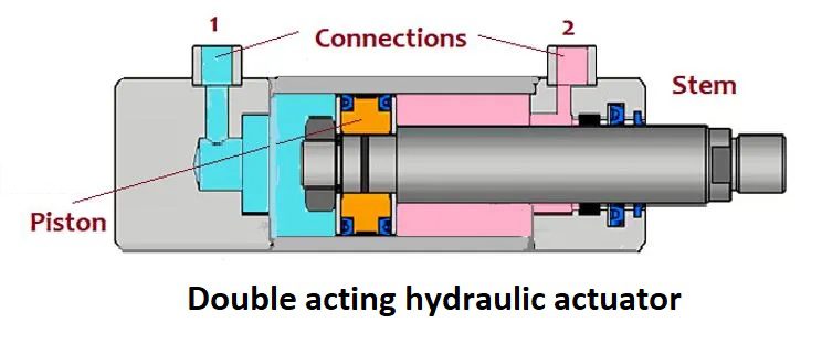
Double acting hydraulic actuator
In double acting actuator, there are two hydraulic ports in such way that controlled oil pressure at one port is used to move actuator open and oil pressure at another port is used to move actuator towards closing. Double acting hydraulic actuators are fail-to-lock type but for ESD trip action, solenoid valves are placed to achieve desired fail safe position. A diagram of double acting hydraulic actuator is shown below-
Application of hydraulic actuator
- Hydraulic actuators are used to operate heavy load applications where high force or high torque is required.
- They are used for applications such as crane drives, winches, self-driven cranes, excavators, wheel motors in military vehicles, feeder drives, agitator drives
- Other applications include- hydraulic jack, hydraulic brake, hydraulic ram etc.
- Closed-loop velocity controlling etc.
Hydraulic and pneumatic actuators
A comparison between sensor and actuators is shown in table-
| Sr. No. | Hydraulic actuator | Pneumatic actuator |
| 1 | Hydraulic actuator is such actuator which uses hydraulic signal or fluid (mostly oil) pressure to move a valve mechanism | Pneumatic actuator is a device which converts the energy of compressed air or gas into a mechanical motion. |
| 2 | Controlled hydraulic oil pressure is used to force a piston. | Controlled pneumatic air pressure is used to force a diaphragm or a piston. |
| 3 | Hydraulic oil pressure used in actuation system can be up to 400 Bar (6000 PSI). | Pneumatic actuators are operated under low pressure of (60 to 100) PSI comparatively. |
| 4 | Hydraulic actuators are used to operate heavy load applications where high force or high torque is required. | Pneumatic actuators are not designed for heavy loads and machinery. |
| 5 | Hydraulic actuators are compact in size because they offer extremely large force for a smaller area too due to high oil pressure. | Due to limitation of pressure, their actuator size is getting bigger to achieve larger force. |
| 6 | Hydraulic actuation system requires very large area to make arrangement of safe and reliable high oil pressure generation. | Pneumatic actuation system requires less space as they operate under low pressure application. |
| 7 | Hydraulic actuators are very efficient. | Pneumatic actuators are comparatively less efficient than hydraulic actuators |
| 8 | Response time of hydraulic actuators is rapid. | Pneumatic actuators exhibit a slightly delayed response time. |
| 9 | Hydraulic actuators are very expensive and require higher maintenance. | Pneumatic actuators are cost-effective and require minimum maintenance |
| 10 | They are used for applications such as crane drives, winches, self-driven cranes, excavators, wheel motors in military vehicles, feeder drives, agitator drives, hydraulic jack, hydraulic brake, hydraulic ram etc.
|
They are used to operate various type of control valves, dampers, louvers, guide vane etc. |
Click on the below links to read more about-
- What is an actuator?
- How “I-to-H Converter” works?
- What is control valve?
- Electric actuator
- What are different types of actuator?
- Sensor Vs Actuator
- Sensor Vs Transducer