Table of Contents
Definition-
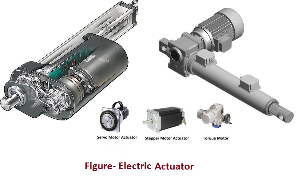
Electric Actuator is such type of actuator that converts electricity into kinetic energy and deliver force or torque to create movement of mechanical load in response of received control signal. Electric actuator basically produces rotary motion because of use of electric motor. Some standard electrical voltage or current supply is used for their operation. Here electric motors may provide continuous rotation or a fixed angular position change. There are different configuration of motor actuator used and application as mentioned below-
- Electric motor actuator
- Stepper Motor actuator
- Servo motor Actuator
- Torque motor
Some standard electric supply used are- 24VDC, 110VDC, 110 VAC, 230VAC etc. Electric actuators are used for large valve application such as damper and guide vanes. Such valve applications along with electric actuators are referred as motor operated valves (MOV). Some different electric actuators are mentioned below-

Types of electric actuators-
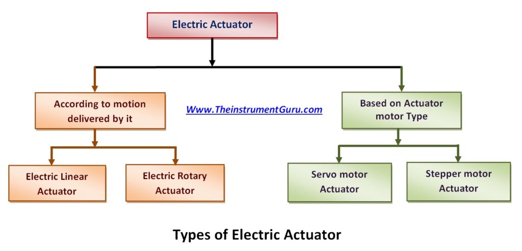
Function of electric actuator is to convert electrical energy into mechanical torque electric actuator working is based on electrical actuation system. Electrical actuator can be classified either according to motion delivered by it or can be based on type of motor used as mentioned below-


Electric linear actuator-
When electric actuator delivers linear motion in response of controlled signal received, it is referred as electric linear actuator. Since motor delivers rotary motion so it is required to convert rotary motion into linear. This is done by means of two main components a gearbox (rotary motion) and a lead screw (linear motion). There are 3 types of lead screws used in electric linear actuators- “Machine Screw, Ball Screw & Roller Screw”. Electric motors rotation drives the primary gear of the gearbox, and gearbox output shaft (final gear) the lead screw and translate rotary motion into linear.
Other electric linear actuators can also use mechanism such as belt drives, geared drives, direct drives, rod type, and rod-less type. Electric linear actuator varies in terms of motor type, power, and features. Linear motors are very similar to rotary electric motors. In a linear motor, the rotor and stator components are laid out in a straight line. So the magnetic field structures of linear motors are physically repeated across the length of the actuator. Electric linear actuators are often preferred when it is required simple, safe and clean movement with accurate precision and smooth motion control. A diagram of electric linear actuator is shown below-


Electric rotary actuator-
When electric actuators provide circular or rotary motion in response of controlled signal applied to it, it is referred as electric rotary actuator. Normally electric motors drive components rotationally via electromagnetic power and speed, transmission line can be controlled with use of gear mechanism. Such actuators typically provide control and indexing capabilities to allow multiple position stops along strokes. The rotational element for rotary electric actuators can be either a circular shaft or a table. Performance parameters for electric rotary actuator includes supply voltage, repeatability, maximum torque, load capacity, linear stroke, operating temperature, and rotation angle etc. Typically, rotation angle of electric rotary actuators can be maximum rotation angle of 45°, 90°, 135°, 180°, 225°, 270°, 315°, or 360°. There are so many applications of these actuators. Some of them are- for semiconductor manufacturing operations, for laboratory or medical use, in the electric power industry, high-power switching gears, and packaging applications, in the automotive industry etc. A diagram for electric rotary actuator is shown below-


Actuator motor-
Linear and rotary both electric actuators use various types of motor for their operation. Actuator motor varies in terms of motor specification such as supply voltage, power, efficiency, travel continuous or discrete type, etc. Various types of linear actuator motor are DC Motor Types, DC brush motors, Brushless DC motor (BLDC), AC Motor Types, AC servomotors, AC stepper motors etc.
- DC Motor type actuator motors are powered by direct current from a battery or DC power supply. The advantage of such motor is that they are able to change rotational direction when the polarity of the input current changes. These motor can be brush type or brushless type.
- In DC brush motors, they usebuilt-in commutation and mechanical brushes that actuate coils on the rotor.
- While in Brushless DC motors,they use an external power drive that allows commutation of the coils on the stator.
- In DC servomotor, ithas an output shaft that is positioned when a coded signal is sent to the motor.
- AC Motor Typesare electric motors powered by alternating current. They convert electrical energy into mechanical energy in order to do work in a system.
- AC motorincludes a wide class of motors including single phase, multi-phase, universal, induction, synchronous, and gear motors etc.
- AC servomotoris permanent magnet synchronous motor that has low torque-to-inertia ratios for high acceleration ratings.
- AC stepper motoruses a magnetic field to move a rotor in small angular steps or fractions of steps.
Servo actuator & linear servo actuator-
Servo actuators are such type of actuator that is used to rotate or push parts of a machine precisely. They are used in variety of applications such as in robotics, electronic actuation, automobiles and airplanes etc. few example of servo actuator is to move the hard drive head arms in computers, to manage the speed management of vehicle, to the throttle to adjust the engine speed, volume control button on radio etc.
A servo system basically a closed loop control system and mainly consists of three basic components – controlled device, output sensor, and feedback system. The major task of a servomechanism is to maintain the output of a system at the desired value. So here feedback signal/ sensor output signal is compared with desired signal and it produces error and controller output is fed to servo mechanism. Servo actuator receives command in form of pulse train. A diagram of servo actuator is shown below-


Stepper motor linear actuator-
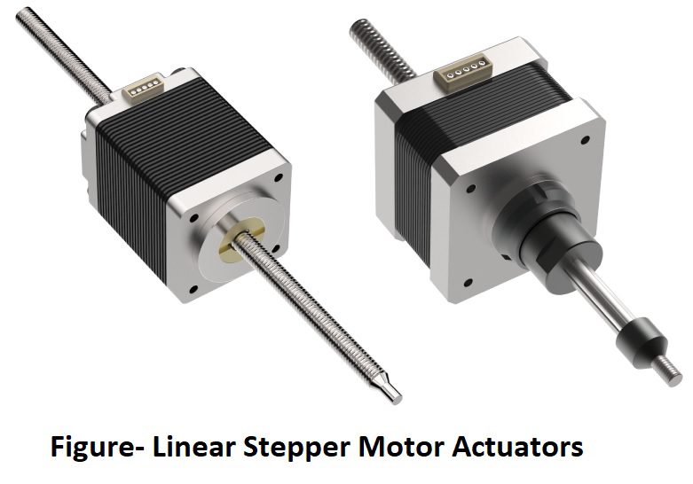
Such linear actuator basically uses a stepper motor. Stepper motor is a brush-less electromechanical motor that converts electrical energy into mechanical energy. The output motion of stepper motor is rotational motion divided into equal number of steps. And the step size selected based on the application requirement. Most Common type of stepper motor actuator is linear type that produces force and motion along a linear or straight path. Here stepper motor used provides precise rotary steps of shaft that is converted into linear motion through a connected lead screw. Stepper motor offers consistent repetition of movement, speed control, and precision in positioning. They are used in so many industrial applications such as 3D printing, robotics, CNC machining, medical imaging, automated machine tools, automotive gauges, surveillance equipment such as cameras, zooming functions in digital cameras etc. A diagram of stepper motor linear actuator is shown below-


Electric actuator valve and Motorized valve actuator-
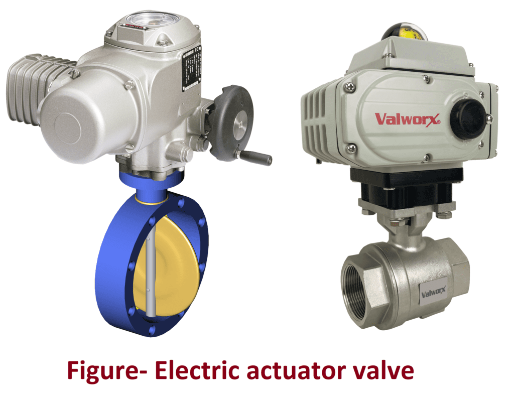
Electric actuator valve basically uses electric actuator to operate valve such as ball valve, butterfly valve and electric actuators are motorized actuator that convert electric energy into rotary force or torque to move valve. Mostly such motorized valve actuator valves are quarter-turn (90 degree) valve actuators. Electric valve actuator uses electric motor to control motion. Motorized valve actuator provides a more energy-efficient and clean method of valve control. The electric actuator valve consists of motor in a compact robust housing, gearing, limit switches, position indicator, manual override, control board PCB, wiring, etc. This motorized actuator is connected to a quarter turn valve through a compatible interface. A diagram of electric actuator valve is shown below-


A diagram showing different parts and components in motorized valve actuator is shown below-


Click on the below links to read more about-
- What is an actuator?
- What is control valve?
- What are different types of actuator?
- Pneumatic Actuator
- Hydraulic Actuator
- Sensor and actuators in IOT
- Sensor Vs Transducer