Table of Contents
Analog and Digital Signals
In this article we will read about the difference between analog and digital signal. Analog and digital signals are used in almost all the operations of electronics. You will be well acquainted with the devices based on digital principle, for example, calculator, watches and computer etc. These instruments have had a great impact on the normal life of man. The main reason for this revolution is the discovery of integrated circuits (ICs) whose development has been possible due to the unlimited advancement in semiconductor technology in the last few years. Most of these people will not be familiar with the working of computers, digital watches or calculators, yet they have become an essential part of our lives. The operation of all these devices is based on digital technology. Read this article in Hindi.
Analog Signals
Analog and digital operation mainly depend on the use of different types of load lines. In analog circuits, points adjacent to the load line are used. Due to which the output voltage is continuous. For this reason the output voltage can have infinite values. The simplest way to obtain analog operation is to use a sinusoidal input. For example, in an electronic amplifier, a continuously varying input to the amplifier produces a continuously varying output. Such continuously changing signals are called analog signals.
Digital Signals
In contrast, almost all digital circuits are designed for two states. This means using two nonadjacent points on the load line. For example: saturation point and cut off point. Using these points only two states of the output voltage are LOW or HIGH. The simplest method of achieving digital operation is to use a square wave input. By using high level of square wave input, it drives the transistor in saturation and cut off state which gives two state output.
This signal is always either LOW or HIGH. This type of signal is called digital signal.
Advantages of digital Signals over Analog Signals | Difference between analog and digital signal
1. The devices used in digital circuits usually operate in either ON or OFF state, which is a simple operation.
2. The number of basic operations of digital circuits is very less and it is easy to understand them.
3. The digital technique is based on Boolean algebra which is a very simple mathematical operation.
4. The working of digital circuits is based on simple electrical circuits. The switching speed and loading characteristics of various devices are used in these circuits. In contrast, analog circuits require frequency characteristic and complicated circuit analysis techniques, due to which these circuits are difficult to understand as compared to digital circuits.
5. Digital circuits are easily available in the form of ICs to perform various operations. It is highly reliable, accurate and their operation speed is high.
6. Variation in characteristics of components, their age, temperature, noise, etc. have little effect on the operation of digital circuits.
7. A special feature of digital circuits is their memory capacity, due to which they are highly suitable for computers, calculators.
Types of Digital Signals
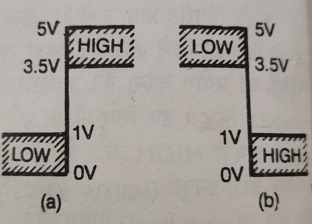
As mentioned above, there are two levels of digital signals. Two different types of digital signals are shown in the photo. Each signal has two discrete levels. These levels are represented by the words LOW and HIGH. In the photo below (a) the low level is marked as LOW and the high level as HIGH while in the photo (b) the high level is marked as LOW and the low level as HIGH .
Positive and Negative Logic System
Such digital circuits in which the signal shown in photo (a) is used are called positive logic systems. Circuits that operate using the signal shown in photo (b) are called negative logic systems. A special thing to note in both types of signals is that the voltage corresponding to the specified level is not constant, but a range of voltage is marked at each level. As long as the voltage remains in this range, its level is also considered to be the same, for example, in positive logic every voltage from 3.5 V to 5 V is considered HIGH and in negative logic it is considered LOW. Thus every voltage from 0 to 1 volt will be considered as LOW in positive logic and HIGH in negative logic. The voltages corresponding to LOW and HIGH levels are not same in all circuits but differ for different logic families.

The high and low levels of a digital signal can also be represented by the binary digits 1 and 0. Binary digits (1 and 0) are called bits. Since the level of a digital signal can be either 1 or 0, the binary number system can be used to analyze digital systems. These two states or levels can also be represented by “1 and 0” or “ON and OFF” or “true and false”.
Hope you liked this article on Difference between analog and digital signal.
Read other articles
- Why Used 4-20 mA?
- 2-wire,3wire and 4-wire Transmitter Wiring
- Fundamental of 4-20 mA loop
- Calibration