Table of Contents
The operating principle of the Coriolis flow meter is very basic but very effective. This phenomenon is all around us in the physical world; For example the rotation of the earth and its effect on the weather.
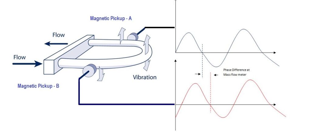
A Coriolis flow meter consists of a tube that is activated by a certain vibration. When a flowing liquid (gas or liquid) passes through this tube the mass flow momentum will cause a change in tube vibration, the tube will bend resulting in phase shift. This phase shift can be measured and has a linear derivative proportional to the output current.
Since this principle measures mass flow independent of whatever is within the tube, it can be applied directly to any fluid flowing through it – liquid or gas – whereas thermal mass flow meters measure the physical properties of the fluid. are dependent. In addition, it is also possible to measure the actual change in natural frequency, in parallel with the phase shift in frequency between the inlet and outlet. This change in frequency is in direct proportion to the density of the fluid – and another signal output can be obtained. It is possible to obtain the volume flow rate after measuring both the mass flow rate and the density.
Coriolis Flow Meter Working principle
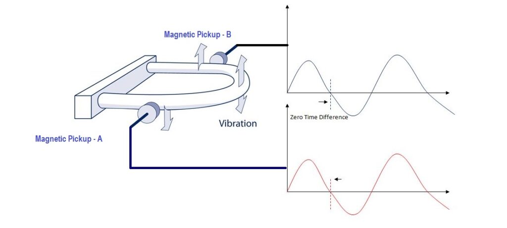
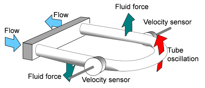
In a Coriolis meter, the Fluid to be measured passes through one or more oscillating tubes; The rate at which mass flow affects the oscillations of tubules, and from this both mass flow and density can be determined. A basic dual tube Coriolis meter consists of two curved tubes through which the current passes. An electromagnetic drive system causes the tubes to vibrate at their resonant frequency toward each other and away like the tines of a tuning fork; The frequency is determined by the stiffness of the tubes and their mass. A pair of electromagnetic coils (called pickup sensors) detect vibrations at points on each side of the drive unit.
If there is no fluid flowing through the tubes, they vibrate away and away from each other in parallel, and are at the output stage of the upstream and downstream motion sensors. But as material flows through the tubes, the Coriolis effect causes the downstream side of the loop to move slightly upward, creating a slight bend in the ends of the tubing. With respect to the velocity of fluid flow through the tubes, the amount of turning and, consequently, the phase difference between the outputs of the upstream and downstream pick off sensors, vary linearly. The phase converges in time, and the time delay is directly proportional to the mass flow. This principle applies regardless of whether the liquid is a liquid, a gas, or a solution.


The natural vibration frequency of tubes is determined by their stiffness and mass. Since the volume of the fluid in the tubes is constant, the change in the density of the fluid causes a change in the mass within the tubes. The natural frequency of the tubes changes when the fluid inside them does, and the pickoff sensor can detect this change. The density of the fluid inside the tubes has a direct impact on the natural frequency. Although temperature measurement is not necessary to determine mass flow, most Coriolis meters include a temperature sensor to compensate for slight changes in tube stiffness (Young’s modulus) with temperature. Temperature is typically introduced with flux and density as the third output variable. Other types of Coriolis meters Coriolis meters with two curved tubes have the highest flow sensitivity. Flow sensitivity is defined as microseconds of phase shift per unit of mass floret – the more signal per unit of flow, the more sensitive the device. Consequently, larger diameter flow tubes and lower pressure drop may be found in metres with higher flow sensitivity. A dual-tube winding meter has the greatest turndown (i.e., the ability to operate at less than 100% capacity) and condensation accuracy, as well as the highest accuracy when handling gases. However, there are two other designs for specialized applications. For use in tight installations, much smaller Coriolis meters are available with tubes that are only slightly curved. However, restricted space reduces flow sensitivity and density accuracy, which in turn reduces usable range and turndown. Because gas flows are low-mass/high-volume applications, high sensitivity is needed for precise measurement, so these metres are not as suitable for them.
Coriolis Flow meter main parts
Let’s start by looking at the main details. There are several types of Coriolis flow meters. Their design may vary, but in general, it consists of several basic elements:
- Tube (tube);
- Sensor;
- Oscillating drive;
- Transducer
Tube:- The tube is an area where basic measurements take place. It is always U-shaped. For improved flow sensitivity, two of these tubes may occasionally be used. A flow splitter is also shown in this instance.It directs half of the main current into each tube.
Sensor:- The sensor is mounted at the input and output of the tube. At the system’s inlet and outlet, they keep track of changes in oscillations.
Oscillating Drive:- The oscillation drive makes a tube vibrate with a constant frequency. The most popular method is the use of pair coils and magnets. In that case, the oscillation is done by the magnetic field. However, they do not need to be equated with electromagnetic flow meters. This is just an auxiliary process. Models with mechanical actuators are also available, but they are less prevalent.
Transducer:- The transducer collects the signals after measuring and converts them into digital or analog data. After that, the results can be shown on the display or forwarded to the control systems. It is always possible to set up additional counters to submit and structure the results autonomously.
Flow Rate and density measurement
After recording changes in oscillations on both sides of the sensor tube, the system proceeds to analyze the acquired information.
With the help of such instruments, the user can measure several parameters at once, including:
- Mass flow
- Density
- Speed
Sometimes sensors can also measure temperature.
The mass flow rate is determined by comparing and analyzing the time delay between two sinusoidal phases. The time interval t is expressed in microseconds (µs).
This parameter is proportional to the mass flow rate. Higher t, higher flow rate.
Density is also measured by analyzing sine waves in the oscillations. When the flux density changes, the oscillation frequency of the tube walls also changes.
Consider this situation on the example of two different loads suspended on the same springs. A larger mass will have a lower oscillation frequency. At the same time, a spring with a smaller load will run more often.
In the case of a flowmeter, the same volume of different substances will have different masses due to their density and act as such weights. Here the tube is the same as the spring in the example. That is, the higher the density of a substance in a current, the lower the wall frequency of oscillations.
According to this principle, the device determines the density of the material being measured.
Coriolis flow meter pressure drop is directly related to flow sensitivity. This value is explained in microseconds of phase shift per unit of mass flow. Therefore, the higher this value, the larger the diameter of the tube and the lower the pressure.
Advantages of Coriolis Flow Meter:
- Accuracy of measurement.
- High repetition.
- No dependence on flow direction
- Lack of moving parts
- Minimum technology required. Service
- Ability to work with very sticky materials
Disadvantages of Coriolis Flow Meter:
- A small range of mobility
- Large dimensions
- External vibration may affect the result
- Sensitivity to temperature changes
Read Also
