Table of Contents
The Full form of RTD is Resistance Temperature Detector. An RTD (Resistance Temperature Detector) is a sensor whose resistance changes as the temperature changes. The resistance increases as the temperature increases. The resistance versus temperature relationship is well known and can be replicated over time. An RTD is a passive device. It does not produce any voltage by itself. External electronic devices are used to measure the resistance of the sensor by passing a small electric current through the sensor to generate voltage. Typically 1 mA or less measuring current, 5 mA maximum without risk of self-heating. If we want to measure temperature with high accuracy, Resistance Temperature Detector is the ideal solution, as it has good linear characteristics over a wide range of temperatures. Other common electronics devices used to measure temperature include a thermocouple or thermistor. Some key points of Resistance Temperature Detector are given below-
- The resistance of an Resistance temperature Detector varies directly with temperature.
- As temperature increases, resistance increases.
- As temperature decreases, resistance decreases.
- RTDs are constructed using a fine, pure, metallic, spring-like wire surrounded by an insulator and enclosed in a metal sheath.
- A change in temperature will cause an Resistance Temperature Detector to heat or cool, producing a proportional change in resistance. The change in resistance is measured by a precision device that is calibrated to give the proper temperature reading.
RTD working principle
A metal resistance element changes its resistance with temp. Pure elements have been used for measurement of temperature by this effect and the method is one of the accurate ones. The relation between the resistance and change in temperature (△t),is expressed by the series
Rt = Ro {1+a(△t) + b (△t)2 + g (△t) 3 + ………+w (△t)n }
Where a, b, g,… w are temp. coefficients of resistance. In the narrow ranges of operation, b and higher order coefficients are negligibly small so that
Rt = Ro {1+a(△t) }
Where a is positive for a metal resistance element and is determined experimentally.
Ro is Resistance at 0(Zero) degree temperature.
Application of RTD:
A Resistance temperature Detector is widely used in process industries for application of temperature measurement. Here, A Resistance Temperature Detector is shown in figure. Size of Resistance Temperature Detector (length, sheath-dia) may change as per requirement/ pipe size.

These RTDs can be used in process for temperature measurement such as-
- Pipeline fluid
- Heat exchangers
- Vessel
- Columns
A schematic diagram for RTD is shown in figure-


Material Of RTD
Different types of materials are used in Resistance Temperature Detector as per applications, uses and requirement of process. Pt( Platinum), Cu (Copper) and Ni(Nikhil) are Most common materials which are used for construction of Resistance Temperature Detector.
The choice of the materials will be governed by
- High temp. coefficient – this gives larger sensitivity
- High restively of the material – this ensures small wire length for high resistance, also a larger resistance for the same wire length and increase output .
- Linearity of relation between resistance and temp.
- Stability of the electrical characteristics of the material and resistance to contamination – this is necessary for good repeatability
- Sufficient mechanical strength- this is necessary as the wire must be drawn very fine for reducing response time and yet must posses adequate ruggedness for construction.
Comparison of relative merits of the materials used in Resistance thermometer:
| Material
|
∝
Ω/Ω/°C |
ρ
μΩ-cm |
Range
°C |
Minimum Dia
Of wire (in) |
Melting point
°C |
Tensile strength
(psi) |
| Pt | 0.00392 | 9.83 | -250 to 700 | 0.002 | 1775.5 | 18000 |
| Cu | 0.0043 | 1.56 | -200 to 250 | 0.002 | 1083 | 30000 |
| Ni | 0.0063-0.0067 | 6.38 | -100 to 350 | 0.002 | 1455 | 120000 |
Use of Wheatstone bridge in Temperature measurement By RTD:
At low range (< 120° K ), a gold-silver alloy has been tried and it has been seen to have the characteristics similar to platinum. For a temp below 7° K,a phosphor bronze alloy shows good change in resistance with temp.
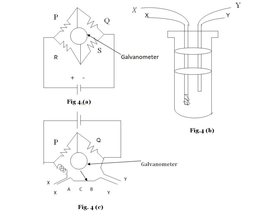
The platinum resistance thermometer works on the principle of Wheatstone bridge used to measure a resistance. In a Wheatstone bridge ,four resistances P, Q, R, and X are joined in a loop as shown in fig . A galvanometer and battery are also joined as shown.


there is no deflection in the galvanometer and the bridge is called balanced. If the condition is not fulfilled ,there is a deflection.
Fig(4-b) represents the arrangement for a platinum resistance thermometer. A thin platinum wire is coiled on a mica base and placed in a glass tube. Two connecting wires YY going through the ebonite lid of the tube are connected to the platinum coil. A similar copper wire XX, called compensating wire, also goes into the tube as shown in fig. A
Wheatstone bridge is arranged as shown in fig(4-c).Two equal resistance P an Q are connected in two arms of the bridge. A copper coil having resistance roughly equal to that of the platinum coil is connected in the third arm through the compensating wire XX. The platinum coil is inserted in the fourth arm of the bridge by connecting the points Y,Y in that arm. The end C of the wire connected to galvanometer can slide on a uniform wire AB of length l. The end A of this wire is connected to the wire XX and the end B is connected to the wire YY. Thus, the copper coil, the compensating wire and the wire AC are in the third arm and the platinum coil, the connecting wire YY and the wire CB are in the fourth arm of the bridge. The test tube containing the platinum coil is immersed in the bath of which we want to measure the temp. The end C is slid on AB till the deflection in the galvanometer becomes zero. Let AC = x
Suppose the resistance of the copper coil connected in the third arm is R ,that of the compensating wire is Rc and that of the wire AB is r. The resistance of the connecting wire YY is the same as Rc and that of the platinum coil is Rt.


RTD Types
Resistance Temperature Detector can be classified on three bases
- Based on sensor.
- Based on connection.
- Based on material used in RTD construction.
1. Based on sensor
Based on sensor RTD comes in two types.
I. Simplex RTD
A simplex RTD Consist of single pair RTD element at its hot end.


II. Duplex RTD
Duplex RTD consist of double pair RTD elements at its hot end instead of a single element in a single enclosure. The main reason such a configuration is to enable Redundancy.


2. Based on connection
Based on connection RTDs Are three Types
I. 2 – Wire RTD
The 2-wire RTD is the least accurate of the three Types, Because there is no way to eliminate the lead wire resistance from the sensor measurement. 2-wire RTDs are typically used with short lead wires or when precision isn’t necessary.


II. 3 – Wire RTD:
The third wire provides a way for reducing the average lead wire resistance from the sensor reading, which is most typically utilised in industrial applications. When there are large distances between the sensor and the measurement/control instrument, a three wire connection instead of a four-wire cable can save a lot of money.


III. 4 – Wire RTD:
4-wire RTD is generally employed in laboratories where high precision is required. The real resistance of the lead wires of a four-wire RTD can be measured and subtracted from the sensor measurement.


Based on material used in RTD construction
Based on the material used in construction of RTD, some types of RTDs are as below.
PT10
It has a 10 ohm resistance at 0 degree centigrade temperature.
PT100
It has a 100 ohm resistance at 0 degree centigrade temperature.
PT500
It has a 500 ohm resistance at 0 degree centigrade temperature.
PT1000
It has a 1000 ohm resistance at 0 degree centigrade temperature.
CU50
It has a 50 ohm resistance at 0 degree centigrade temperature.
CU100
It has a 100 ohm resistance at 0 degree centigrade temperature.
Ni1000
It has a 1000 ohm resistance at 0 degree centigrade temperature.
RTD Protection
For RTDs element protection from direct temperature/ fluid exposure and replacement purposes (When RTD is faulty), Thermo well are placed for mounting RTDs. Some different type of thermowell are shown below-
Why Thermowell Used??
There are some reason why to thermowell need to be used.
Protective Barrier
A thermowell’s main job is to protect a RTD from external conditions, which it does by housing the RTD, as shown in Figure. With the RTD safe inside, the thermowell can handle an assortment of corrosive or abrasive process media and withstand turbulent or high pressure conditions. The thermowell prevents the RTD’s sensing element from being exposed to extreme hot or cold temperatures.
Increased Serviceability
If you need to remove or replace a RTD, thermowells simplify the process by providing easy access. They stay installed in the piping system while a RTD is being serviced. As a result, operations continue, which means there is no unnecessary downtime, and the process media continues to flow without worry of escaping the system.
Reduced Operational Costs
RTDs last longer and do not need to be serviced as often when thermowells are used to protect them. In effect, thermowells help decrease the total cost of RTDs by minimizing the time spent maintaining and servicing the instruments. The fact that you won’t need to replace RTDs as often or maintain a large inventory of them will also save you money in the end.
Some Technical Word For Thermometer That YOU should Know
- Thermowell root dimension (Q)
- Thermowell Immersion (“U”) Length
- Thermowell Lagging Extension (“T”) Length


Note:- A special type RTD is used to measure bearing temperature in Rotating Machine such as compressor, turbine called as PIN type RTD. Working and operation are same but design is different. Pin type RTD also comes in simplex and duplex.
Pin type RTD shown in Figure.


RTD wiring Diagram :-
How RTD works and how its resistance is calculated. Everything has been explained in detail above now how to measure temperature by RTD. It is known that to measure temperature through RTD, RTD is connected through proper wiring through a temperature measuring device. Which is shown below –
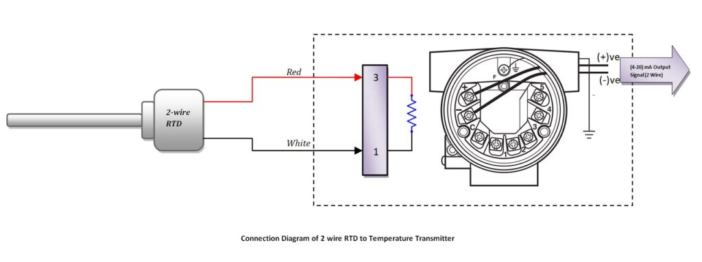
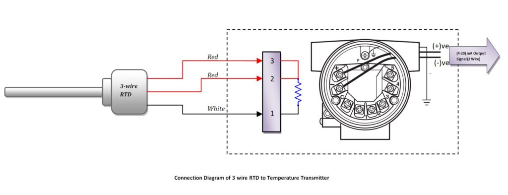
1. RTD Connection with Transmitter
The connection of the RTD with the transmitter is required when the signal is to be sent far away. The distance between Resistance Temperature Detector and control room should be more.
2 Wire RTD Connection with Transmitter


3 Wire RTD Connection with Transmitter


4 Wire RTD Connection with Transmitter


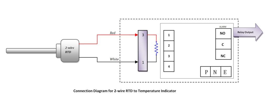
2. RTD Connection with indicator:
The connection of the RTD with the indicator is very common. This connection is also done in many industries or local instruments. If the room temperature is being measured by RTD then the connections will be in the indicator itself.
Generally, if the temperature is to be measured through Resistance temperature detector in the local, then the indicator is used. And its connections are shown below –
2 wire RTD Connection with indicator


3 wire RTD Connection with indicator


4 wire RTD Connection with indicator


Read Also
