Table of Contents
“Pneumatic actuator is a device which converts the energy of compressed air or gas into a mechanical motion. Here motion delivered can be rotary or linear, depending on the type of actuator. Pneumatic actuators are known for highly reliable, efficient, and safe sources of motion control.”
A Pneumatic actuator diagram is given below showing different configuration-

Pneumatic actuator Valve
A pneumatic actuator converts pneumatic energy into mechanical energy that regulates a final control element such as control valve according to the control signal received. Pneumatic actuator used for operating control valves are termed as Pneumatic actuator Valve. Typically in industries, pneumatic systems utilize air pressures of (80 to 100) PSI for their operation. Actuator valve mainly consists of a diaphragm or a piston enclosed by a casing and a stem connected to the diaphragm or piston which can be linked to a valve stem via coupling. They can have either one pneumatic signal port along with spring return mechanism which is referred as single acting actuator or can have double pneumatic signal port which is referred as double acting actuator. Beside that according to valve type, linear or rotary actuator is connected. A diagram for simple pneumatic actuator valve is shown below-


Types of pneumatic actuators
Pneumatic actuator utilizes energy of compressed air for their operation. they can be classified as mentioned below-


Pneumatic linear actuator
When pneumatic actuators deliver linear motion in response of controlled air pressure applied to it, it is referred as pneumatic linear actuator. Mostly such actuators are used for glove valve application to precisely regulate fluid flow and gate valve too. A diagram of linear actuator with globe valve and gate valve application is shown below-


Pneumatic rotary actuator
When pneumatic actuators deliver rotary motion in response of controlled air pressure applied to it, it is referred as pneumatic rotary actuator. Normally rotary actuator can turn to 90 degrees (quarter turn) during full scale movement. They are used to operate ball valves, butterfly valves. A diagram for pneumatic actuated ball valve is shown below-


Diaphragm actuator
Diaphragm actuator is pneumatic actuator that uses a compressed air supply and normally used to operate control valves such as globe valve, butterfly valve according to control signal received. Typically it is used to regulate the fluid in order to adjust some process variables, such as pressure, fluid level, temperature, flow rate etc. They are used in process industries, oil and gas industry, refineries. A diagram for simple diaphragm actuator along with its parts /components is shown below-


Pneumatic actuators basically consist of a rubber diaphragm with spring return mechanism enclosed in a metallic casing. When a controlled air pressure is applied at signal port (at one end of diaphragm) , diaphragm expands and spring compression occurs and hence actuator stem travels.
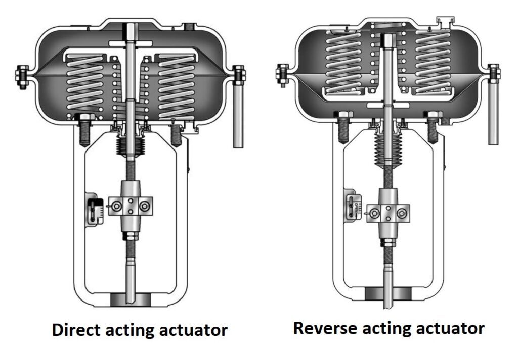
Diaphragm actuator is available in single acting type because the air is only supplied to one side of the diaphragm, and they can either be direct acting (spring-to-retract) or reverse acting (spring-to-extend). There are two possible configuration exists- “Direct Acting” (spring-to-retract) and “Reverse Acting” (spring-to-extend) as shown below-


In direct action, the air enters from the top area (at input port) of the diaphragm and pushes the diaphragm down against spring. Direct-acting types are suitable for air-to-close (ATC) and fail-open (FO) applications.
While in reverse action, the air supply port is located under the diaphragm that pushes the diaphragm upside against spring. Most of the control valve actuators are reverse-acting type because they offer fail safe mode as valve closed position, i.e. air-to-open and fail-closed (FC) condition.
Pneumatic piston actuator
Pneumatic actuator is a device that transforms energy of compressed air into motion according to control signal applied. While using diaphragm actuator, there is limitation of short stroke length and small thrust due to diaphragm. To get a larger stroke length and high thrust, we use a sealed piston enclosed in a metallic cylinder. Here desired stroke length can be achieved by changing length of cylinder and desired thrust can be achieved by changing inner diameter of cylinder. Piston actuator can be either single acting type in which there is one signal port along with spring return mechanism or double acting type in which two air ports available. Piston cylinders are used for larger stroke application (such as damper actuator). A diagram of 2 different configurations of piston actuator is shown below-


A diagram showing different part and components is shown below-


Rack and pinion actuator
Another type of pneumatic actuator is Rack & pinion actuator which is used for mostly on-off application (i.e. to open and close valves) of quarter-turn valves like Butterfly, Ball, Plug valves & dampers usually in industrial applications. “Rack and pinion” is a generic term for a pair of gears which convert linear motion into rotational motion. A linear gear bar called “the rack” engages teeth on a circular gear called “the pinion”. Linear force exerted on the rack will cause a rotational motion of the pinion. A figure showing simple rack and pinion mechanism is mentioned below-


“Rack & pinion mechanism uses two piston-type racks moving in opposite directions to ensure balanced forces on the pinion. Typically, pneumatic air pressure is used to power the actuator. By applying pressure to the piston racks, the pinion can be turned to the desired position. The pinion bottom connects to the valve stem to open and close the valve as the pinion turns. These actuators are available in two constructions-
- Spring Return- Mechanical Spring Return is for fail-safe applications and can be assembled for “Fail Close” or “Fail Open” safety function, and
- Double Acting- Double Acting actuators can be used for a “Fail to lock Position” safety function.”


Scotch yoke actuator
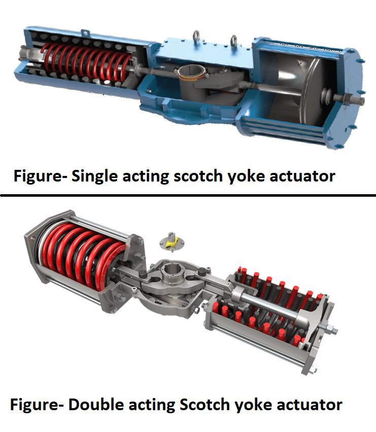
This actuator uses scotch yoke mechanism for their operation and converts linear force into torque to motorize quarter turn valves. There are two configurations available- “Single acting and double acting”. Scotch yoke actuator consists of 2 main components- housing containing yoke mechanism, pressure cylinder containing piston. In single acting type spring is also become part of it where as in double acting there is no spring and air pressure requires for both- closing as well as opening too. A diagram of scotch yoke actuator is shown below-


Vane actuator
Vane actuators are basically true rotary pneumatic actuators and do not require the conversion of a linear motion to a rotary motion. They are used to open, close, or modulate quarter-turn valves, dampers, louvers, and for precise movement of inlet guide vane of compressor or turbine as well as ergonomic lifting equipment. The vane actuator shaft is designed to connect directly over valve devices for the transfer of movement. A diagram of vane actuator is shown below-


Single acting actuator or Spring actuator-
In single acting actuator, control pressure is applied at one inlet port of actuator to operate/ open the valve, and valve closing is determined by stored energy of spring. That’s why single acting actuator is also referred as spring actuator. For closing of valve, the applied pressure proportionally is decreased and it is guided by spring return/ spring release. There are two type of possible action (without use of air lock relay)-
- Direct Acting Actuator (Apply pressure to open/ Fail close)
- Reverse Acting Actuator (Apply pressure to close/ Fail open)


When applied control pressure to actuator is used to open valve and energy at spring return used for safe valve closing, it is called as direct acting actuator. In direct acting actuator control signal failure results to close valve as fail safe action. When applied control pressure to actuator is used to close valve and energy at spring return used for safe valve opening, it is called as reverse acting actuator. In reverse acting actuator control signal failure results to open valve as fail safe action.
However, Fail to Lock position can be achieved by installing Air lock relay so that when control signal fails, pressure applied to actuator should be constant to hold/ lock the valve at same position.
Double acting actuator
In double acting actuator, there are two signal ports in such way that controlled pressure at one port is used to move valve open and controlled pressure at another port is used to move valve towards closing. Mostly double acting actuator are fail to lock type. However fail open & fail close condition can also be achieved by using control valve accessories such as valve positioner and solenoid valve etc.
Pneumatic actuator applications
There are a wide field of applications of pneumatic actuator in process plants and industries. Now a day’s such actuators are also integrated with electronic devices using solenoid valve, positioner, I/p converters etc. so that they can take command directly in electric form from digital controllers via manipulating signal output. Some of their field of applications are as follows-
- Chemical plants and refineries
- Water treatment plants
- Manufacturing industries
- Food handling industries
- Electronic industry
- Automotive industries
- Agriculture applications
- Construction and coal mining equipment etc.
Advantages of pneumatic actuator-
- Pneumatic systems run on air pressure, a safe fluid medium.
- All types of fail-safe positions are available and can be configured with pneumatic actuator.
- Pneumatic control equipment is widely available and relatively inexpensive.
- Pneumatic control systems can be configured to achieve a vast range of functions.
- Heavy-duty pneumatic actuators can be used for modulating applications.
- Pneumatic actuators allow very high-speed operation.
- Pneumatic actuators are preferred for small to medium size valve application.
Disadvantages of pneumatic actuator-
- At present, pneumatic actuators are not easily integrated into electronic database management.
- As valve size increases, pneumatic actuator size also increases, which leads slow operation of valve.
- For a larger size of actuator, larger pneumatic cylinders are used, storing very high air volumes, leading to more energy costs for compressed air and high weight impacting on piping construction support.
- Pneumatic actuators are typically more costly than equivalent torque electric actuators considering uses of control components such as solenoid valves, air filter regulators and other pneumatic instrumentation.
Click on the below links to read more about-