Table of Contents
What is OSI Model:- Open System Interconnection (OSI) is an acronym for Open System Interconnection. In 1984, ISO – the International Organization for Standardization – established the OSI Model, which is today used as an architectural model for inter-computer communications. The OSI Model is a seven-layer design with distinct functions for each tier. All seven levels work together to send data from one person to another around the world.

The OSI model breaks the process down into seven smaller, more doable steps. A unique task is assigned to each layer.
Each layer is self-contained, allowing each layer’s activities to be completed individually.
Characteristics of OSI Model:
There are two layers in the OSI model: upper layers and lower layers.
The OSI model’s upper layer mostly deals with application-related difficulties and is only implemented via software. The application layer is the one that is closest to the user. The software application is interacted with by both the end user and the application layer. The layer directly above the other is referred to as an upper layer.
The OSI model’s bottom layer deals with data transit difficulties. Hardware and software are used to implement the data link and physical layers. The physical layer is the OSI model’s lowest layer, and it’s the one nearest to the physical media. The physical layer is primarily in charge of retaining data on the physical medium.


Functions of OSI Layers:
The OSI model comprises seven layers. Each layer has a distinct purpose. Below is a list of the seven layers:
- Physical Layer
- Data-Link Layer
- Network Layer
- Transport Layer
- Session Layer
- Presentation Layer
- Application Layer
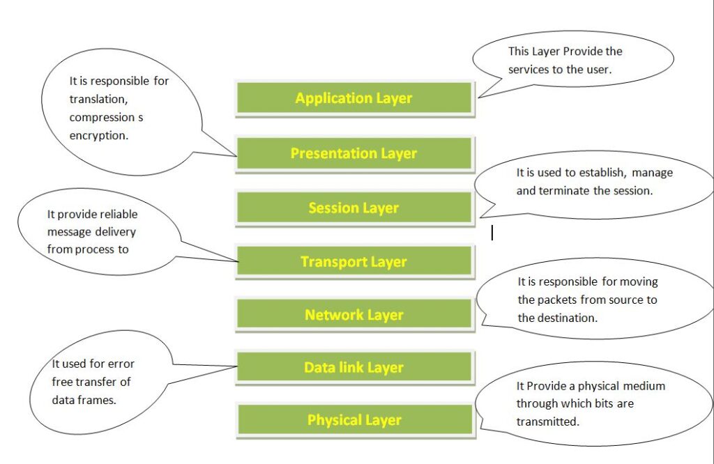
1. Physical Layer:-
The physical layer is the lowest layer in the OSI reference model. It is in charge of establishing a physical connection between the devices. Bits of information are stored in the physical layer. It’s in charge of sending individual bits from one node to the next. When receiving data, this layer receives the signal and converts it to 0s and 1s before sending it to the data link layer, which reassembles the frames.
The functions of the physical layer:
- Bit Synchronization:A clock provided by the physical layer allows bits to be synchronized. This clock controls both the sender and the receiver, ensuring bit-level synchronization.
- Bit rate control: The physical layer also controls the transmission rate, or how many bits are transferred each second.
- Physical Topology:The physical layer defines how the various devices/nodes in a network are organised, such as bus, star, or mesh typologies.
- Transmission Mode:The physical layer also governs how data is passed between two connected devices. Simplex, half-duplex, and full-duplex transmission modes are available.
Physical layer devices include hubs, repeaters, modems, and cables.Lower levels or hardware layers are the network layer, data connection layer, and physical layer. 
2.Data Link Layer(DLL):
The data link layer is in charge of message transport from node to node. The major purpose of this layer is to ensure that data movement from one node to another is error-free at the physical layer. It is the role of the DLL to send a packet to the host using its MAC address when it comes in the network.
There are two sub layers in the data link layer:
- Logical Link Control (LLC)
- Media Access Control (MAC)

Based on the frame size of the NIC, packets received from the network layer are further divided into frames (Network Interface Card). The sender and receiver’s MAC addresses are also encapsulated in the header by the DLL.The MAC address of the receiver is retrieved by sending an ARP (Address Resolution Protocol) request over the wire with the question “Who owns that IP address?” And the MAC address of the destination host will be returned.
Functions of the Data Link layer
- Framing:- The data link layer’s framing function is crucial. It allows the sender to deliver a group of bits to the receiver that are relevant to the receiver. This can be done by adding specific bit patterns to the frame’s beginning and finish.
- Physical addressing:- After producing frames, the Data link layer adds the sender and/or receiver’s physical addresses (MAC addresses) to the header of each frame.
- Error control:- The data link layer provides error control by detecting and retransmitting damaged or lost frames.
- Flow Control-: Because the data rate on both sides must be constant or the data would be damaged, flow control coordinates the amount of data that can be sent before getting acknowledgement.
- Access control:- When many devices share a single communication channel, the data link layer’s MAC sub-layer assists in determining which device has control over the channel at any particular time.
3.Network Layer (Layer-3)
The network layer is responsible for data transmission between hosts that are connected to various networks. It also handles packet routing, which is the choosing of the shortest path to send a packet from a large number of options. The network layer places the IP addresses of the sender and receiver in the header.

The Network layer performs the following tasks:
(I). Routing: The network layer protocols determine which path from source to destination is most appropriate. Routing is the name for this network layer function.
(II). Logical Addressing: The network layer establishes an addressing system in order to uniquely identify each device on the network. The network layer places the IP addresses of the sender and receiver in the header. Each device is individually and universally identified by such an address. * Packet is a network layer segment.
** Networking devices, such as routers, implement the network layer.
4. Transport Layer (Layer-4)
The application layer receives services from the transport layer, while the network layer receives services from the transport layer. Segments are the units of data in the transport layer. It is in charge of the full message’s delivery from beginning to end. If an error is detected, the transport layer acknowledges the successful data transmission and re-transmits the data.

On the sender’s side: the Transport layer takes prepared data from the upper layers, performs segmentation, and implements Flow and Error Control to assure proper data delivery. In addition, it inserts Source and Destination port numbers to its header and sends segmented data to the Network Layer.
Note that the sender must be aware of the receiver’s application’s port number.
This target port number is usually set, either automatically or manually. When a web application makes a request to a web server, for example, it normally uses port 80, which is the default port for web applications. Default ports are assigned to many apps.
On the receiver’s end:The Transport Layer reads the port number from its header and passes the data to the appropriate application. It also does data segmentation, sequencing, and reassembling.
The transport layer’s functions are as follows:
- Segmentation and Reassembly: This layer takes the message from the (session) layer and divides it down into smaller pieces. A header is attached to each of the segments created. The message is reassembled by the transport layer at the destination station.
- Service Point Addressing: The transport layer header includes a form of address called service point address or port address in order to deliver the message to the relevant process. The transport layer ensures that the message is delivered to the relevant process by supplying this address.
The transport layer provides the following services:
(A). Connection-Oriented Service: This is a three-phase procedure that starts with
- Connection Establishment
- Data Transfer
- Disconnection / Termination
After receiving a packet or series of packets, the receiving device sends an acknowledgement back to the source in this form of communication. This method of transmission is secure and trustworthy.
(B). Connection less service: This is a one-step procedure that incorporates data transfer. The receiver does not confirm receipt of a packet in this sort of transmission. This method enables for substantially faster device-to-device communication. One that is connection-oriented is more reliable than service that is not.
Segments are the units of data in the Transport Layer. The Operating System is in charge of the Transport Layer. It is a component of the operating system that uses system calls to communicate with the Application Layer.
The Transport Layer is referred to as the “heart” of the OSI model.
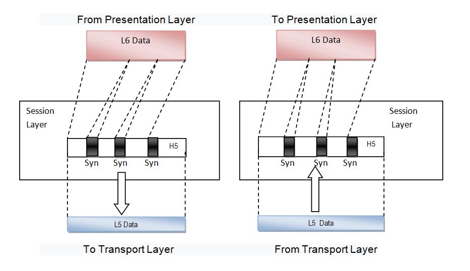
5. Session Layer (Layer-5):
This layer is in charge of establishing connections, maintaining sessions, authenticating users, and ensuring security.
The session layer’s functions are as follows:
(I). Establishment, maintenance, and termination of sessions: The layer enables the two processes to create, use, and terminate connections.
(II). Synchronization: This layer allows a process to insert checkpoints into the data that serve as synchronization points. These synchronization points aid in the detection of errors so that data may be correctly re-synchronized, message ends are not severed prematurely, and data loss is avoided.
(III). Dialog Controller: The session layer enables half-duplex or full-duplex communication between two systems.
**In the TCP/IP architecture, all three layers (including the Session Layer) are combined into a single layer called “Application Layer.” The network application is responsible for implementing these three layers. These are also referred to as Software Layers or Upper Layers.
Consider the following scenario: A user wishes to send a message using a Messenger programme that is running in his browser. In this case, the “Messenger” serves as the application layer, providing the user with an interface to create data. This message, or “Data,” is compressed, encrypted (if any secure data exists), and transformed to bits (0s and 1s) before being sent.
6. Presentation Layer (Layer-6)
The translation layer is also known as the presentation layer. The data from the application layer is retrieved and processed here so that it may be transmitted across the network in the proper format.

The presentation layer’s functions are as follows:
(I). Translation: for example, ASCII to EBCDIC conversion.
(II). Data Encryption/Decryption: Data encryption converts data into a different format or code. The ciphertext is the encrypted data, and the plain text is the decoded data. When encrypting and decrypting data, a key value is used.
(III). Compression: Reduces the amount of data that must be sent over the network
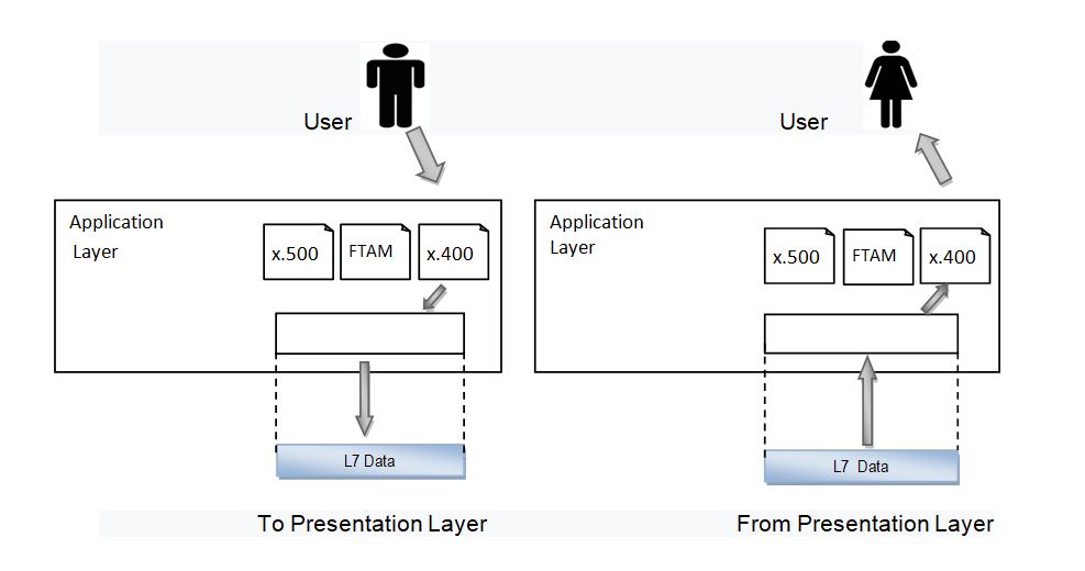
7. Application Layer (Layer-7)
The Application layer, which is implemented by network applications, is at the very top of the OSI Reference Model stack of layers. These programmes generate the data that must be sent across the network. This layer also acts as a window for application services to connect to the network and show the information they receive to the user.
Browsers, Skype Messenger, and other applications are examples.
**The Desktop Layer is also known as the Application Layer.
The Application layer has the following functions:
(I). Network Virtual Terminal
(II).FTAM (File Transfer Access and Management) is a programme that allows you to access and manage files.
(III). Mail Services
(IV).Directory Services
Because of its late creation, the OSI model serves as a reference model and is not deployed on the Internet. The TCP/IP model is the one currently in use.
How data flows through the OSI Model
Human-readable data must go down the seven layers of the OSI Model on the sending device and then up the seven layers on the receiving end in order to be exchanged over a network from one device to another.
Mr. Raman, for example, wishes to send Ms. jay an email. Mr. Raman types his message into an email programme on his laptop and then presses the’send’ button. His email application will send his message to the application layer, which will select an appropriate protocol (SMTP) and send the data to the presentation layer. The data will be compressed by the presentation layer before being transferred to the session layer, which will start the communication session.
The data will then be segmented at the sender’s transportation layer, and those segments will be broken down even further into packets at the network layer, which will be broken down even further into frames at the data link layer. The physical layer will next turn the data into a bitstream of 1s and 0s and transport it across a physical media, such as a cable, after the data link layer has delivered those frames.
When Ms. jay’s computer receives the bit stream over a physical channel (such as her wifi), the data flows through the identical series of layers on her device, but in reverse order. The physical layer will first convert the bitstream into frames, which will then be transmitted to the data link layer. The frames will subsequently be reassembled into packets for the network layer by the data link layer. The network layer will next split the packets into pieces for the transport layer to reassemble into a single piece of data. The data will next flow onto the receiver’s session layer, which will send it on to the presentation layer before terminating the communication session. The presentation layer will then decompress the data and send it up to the application layer as raw data. Ms. jay’s email software will then receive the human-readable data from the application layer, allowing her to view Mr. Raman’s email on her laptop screen.
Read Also