Table of Contents
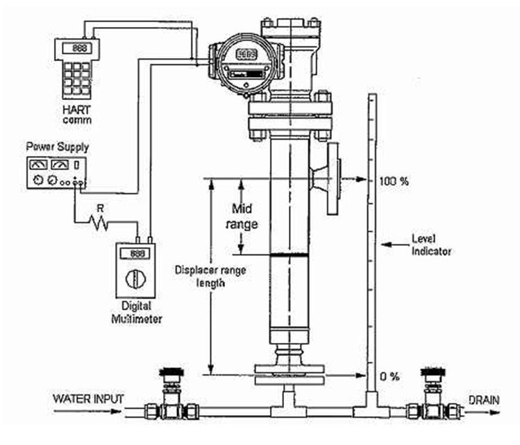
Displacer/Level Troll Level Transmitter or any other buoyancy level transmitter uses the effect of buoyancy. When the displacer is immersed into the process fluid, the buoyancy effect will make the displacer lighter than the non immersed displacer. Change of displacer weight detected by the sensor (Torque tube or LVDT) and then translated into the fluid level.
Before we calibrate the displacer level transmitter, we must aware that the transmitter has been set at the factory as per process fluid specific gravity, while we will use water as calibration fluid. When the displacer is operated by using actual process fluid, it will show 4 mA at zero levels (Displacer not immersed into fluid) and 20 mA at a high level (displacer fully immersed into the fluid.) Thus before we calibrate the transmitter, we need to calculate the equivalence of buoyancy effect if we use water for calibration instead of using actual process fluid.

Example:
Non-interface Displacer Level transmitter Calculation
Level Transmitter Travel range is =0 to 1000 mm
Water specific gravity= 1
Process fluid specific gravity=0.89
Equivalence zero level using water (4mA)
= (process fluid specific Gravity/water specific gravity)* low range of transmitter
= (0.89/1)*0 mm
LRV =0 mm
Equivalence high level using water (20mA)
= (process fluid specific Gravity/water specific gravity)*High range of transmitter
= (0.89/1)*1000 mm
URV =890 mm
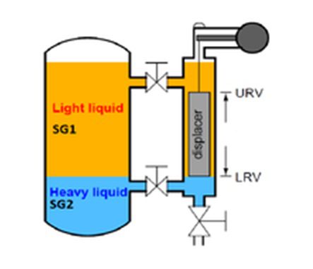
Interface Displacer Level transmitter Calculation


Level Transmitter range is =0 to 1000 mm
Water specific gravity= 1
Lighter process fluid specific gravity (SG1) = 0.63
Heavier Process fluid specific gravity (SG2) =0.89
Equivalence zero level using water (4mA)
= (lighter process fluid specific Gravity/water specific Gravity)* High range of transmitter
= (0.63/1)*1000 mm
LRV =630 mm
Equivalence high level using water (20mA)
= (Heavier process fluid specific Gravity/water specific Gravity)*High range of transmitter
= (0.89/1)*1000 mm
URV =890 mm